
Serial LCD Kit Quickstart Guide
Overview:
The Serial LCD Kit includes all the parts you need to add a serial "backpack" to a 16x2 LCD. The kit includes a pre-programmed ATmega328 microprocessor, which reads a serial stream of data and (after a little heavy-lifting) instantly displays it on the LCD. Interfacing the Serial LCD with an Arduino, or other serial-enabled devices, allows you to easily print GPS coordinates, short messages or any other information onto the LCD.
This tutorial will cover everything you need to know to get up and running with the Serial Enabled LCD Kit. We'll first go over assembly so you can turn that bag-o-parts into something that hopefully resembles any pictures you may have seen of the kit.
Following assembly, we'll touch on how to actually use the Serial LCD Kit. Specifically, we'll go over how you'd use the thing with everybody's favorite development board, Arduino. There'll be example code galore, and you can even make your own LCD clock! It's gonna be pretty crazy...
Requirements:
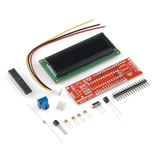
First and foremost, you need the Serial LCD Kit, and everything that comes with it:
- 1x Serial Enabled LCD Kit PCB
- 1x ATmega328 with Serial LCD Firmware
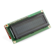
- 1x 5V White on Black 16x2 LCD w/ Backlight
- 1x 16MHz Crystal
- 1x 2N3904 NPN Transistor
- 1x 10kΩ Trimpot
- 2x 0.1μF Ceramic Capacitors
- 2x 22pF Ceramic Capacitors
- 1x 10μF Electrolytic Capacitor
- 1x 10kΩ Resistor
- 1x 16-pin Straight Male Header
- 1x 3-Wire Jumper Cable with JST Connector
Missing any parts? (Bad SparkFun kitters!) Drop our customer service team an email. We'll get them out to you as soon as possible.
At a minimum, the required tools for assembly are a really basic soldering iron, a bit of solder, and some cutters. In addition to those tools, other items you might find helpful include needle nose pliers, and perhaps a third hand, or vise, to keep everything nice and stable.

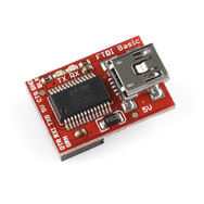
Finally, you'll need something to send a serial stream of data to the display. An Arduino works great (any variety, this isn't limited to the Uno) if you want to automate the serial data stream. FTDI breakouts or RS-232 level shifters work if you just want to connect the display to your computer and send data via a terminal program. For what it's worth, this tutorial will focus on connecting the display to an Arduino.
What it Does:
The goal of the Serial LCD Kit is to make controlling an LCD simple and to make wiring to it even simpler. If you wanted, you could abstain from using the serial backpack and wire an Arduino directly up to the LCD. To that point, there are loads of great examples, and even some Arduino libraries, that make interfacing a microcontroller directly to an LCD very easy. However, because the LCD is driven by a parallel interface, those examples require a tangle of wires and anywhere from 6 to 11 pins of the Arduino to control the thing.

The microcontroller on the Serial LCD Kit takes care of all of that nasty wiring, so you only need one pin to control the LCD. The Serial LCD's on-board microcontroller parses any incoming commands or characters, and then sends the proper data to the LCD over the multi-wire parallel interface. It's a magic black box, and you don't have to care how it does its job, just that it does it. So let's get it built...
How to Use it:
Assembly:
What you've got in front of you right now is not yet a Serial LCD Kit. First, we've got to turn that bag of parts into a Serial LCD Kit, which will require soldering. If you've never soldered before, don't fret! This is one of the easier soldering projects, every part is through-hole, and well-spaced. If this is your first time though, I'd encourage you to take a trip over to one of our excellent soldering tutorials before picking up the iron.
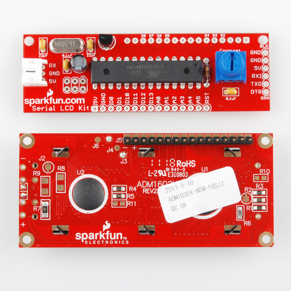
First, pick out the big, ferrari-red PCB. See how one side has white silkscreen printed onto it? This is the top of the PCB. You'll stick almost every part in on this side and solder the pins to the opposite side. The only time we'll stray from that is when soldering the LCD, which is the last step.

It's pretty obvious where each part goes, but consult the diagram above if you're confused.
We'll solder the lowest-profile parts first, so single out that little 10kΩ resistor. Bend it into a 'U' shape and guide the two legs through their mating holes. Now just flip the board over and solder both legs to the bottom of the PCB. If the resistor keeps falling out before you can get it good and soldered, bend the legs out a little bit to better secure it. Try to keep the part as flush as possible with the PCB. After soldering, make sure you clip the excess of the legs as close to the solder joint as possible.
Next, find all four of the yellow ceramic capacitors, and separate them by their 3-digit code. “104” means 0.1uF, while “220” signifies 22pF. Don't mix these up. Stick the caps into their corresponding, rectangular footprint, flip over the board and solder up both legs. Clip the excess legs. Follow the same process for the white, three-pin JST connector, and the silver, oval crystal.

Pick out the 10uF electrolytic capacitor. It's a little black, can-looking part. Before plugging it into the board, notice that one of the legs is shorter than the other. Whenever you see this asymmetry, consider it an alert that the part is polarized, which means, in order for the part to work correctly, you have to assemble it in a very specific direction. In this case, the shorter leg signifies the negative pin of the capacitor. If you look closely at this capacitor's landing spot on the PCB, you'll notice an inviting white dash which marks the negative pin. Match up the negatives and follow the same soldering/clipping process as usual.
The transistor is also polarized, though all the legs are the same length. This time notice that the package comes in something of a half-circle shape. Pretend you're plugging a half-circle peg into a half-circle hole, and match up the flat edge of the transistor, with the flat edge printed on the PCB. Solder it just like usual, and work those clippers.
 Now the big-daddy, the ATmega328. Also polarized! This time there's a notch on the chip, which you'll match up to the notch on the parts landing spot on the PCB. You've got 28 pins to solder this time. Enjoy! Soldering is really just paint-by-number, with the coloring pencils replaced by a scalding iron, isn't it?
Last, you'll do up the big, blue trimpot. This part's polarized, although it'd work either way. You might as well match up the part to the footprint on the board, though. There's a couple notches on one side of the pot that you can match up to the board. Solder, clip, and dance! You're done.
Wait...something's missing...oh, hi LCD! To connect the LCD to the PCB, we've included a straight 16-pin header with the kit. You'll need to solder this header to both the PCB and the LCD. Solder it first to the LCD, stick the shorter pins into the LCD. Make sure the longer legs are extended out from the back of the LCD and solder all 16-pins on the top side of the LCD. Effort to keep the pins as perpendicular to the LCD as possible.
Notice the 16-pin header soldered into the LCD.
With the header soldered to the LCD, you'll finally be able to connect the display to the PCB. Remember, we're sticking this part into the bottom side of the PCB, and soldering to the top. Solder up all 16 pins, and that should be it.

Hardware:
Before you can display anything on the LCD, you'll have to connect something to it. Only three wires are necessary to use the Serial LCD Kit: RX, GND and VCC. Plug the included 3-wire jumper cable into its mating JST connector that you soldered onto the PCB. This color coded cable has two wires for power, and one for receiving serial data. The red and black wires correspond to +5V and GND, respectively, and the yellow wire is RX.
You'll need to figure out how you're going to power the LCD Kit. It doesn't have a regulator on-board, so it's up to you to supply a clean, regulated 5V power source. If you're using an Arduino, you could power the Kit off of the 5V and GND pins – connect red to 5V and black to GND. Otherwise, there's a ton of options out there for power; you could use a USB adapter, a 5V wall-wart, a breadboard power supply. The list just goes on. Just make sure you're not supplying any more than 5V (a little less may work, but you'll lose some brightness).
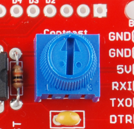
After powering the Serial LCD Kit, you should notice the backlight turn on. If the contrast is properly adjusted, you might see the splash screen flash for a second or two. Most likely though, the contrast won't be set correctly, so you won't see a splash screen. In that case, you may see anything from 32 white boxes to absolutely nothing. You'll have to be quick about it, because the splash screen only remains for a couple seconds before going blank, but try turning the trimpot knob until you've got a good view of the characters on the LCD.

The 'Serial' in the Serial LCD Kit can be a little confusing. What it really means is TTL serial, not to be confused with RS-232 serial. The voltage on the RX line should only go between 0 and +5V. If you're using a microcontroller (like an Arduino) to talk with the LCD, then you most likely don't have to worry. Just don't hook up a PC's serial port straight to the LCD and expect it to survive.
There's a lot of components that are capable of sending TTL serial data. The most popular here at SparkFun are USB-to-Serial boards (like the FTDI Basic Breakout), or an Arduino. This tutorial is going to assume you have an Arduino for the next few examples. No Arduino? That's cool. I get it; you're not gonna conform to this passing fad. Feel free to read on, and try to port these examples to your platform.
Connect the Arduino to the Serial LCD as follows. If you have a wire stripper, you may want to expose a few millimeters more of wire to allow them to stick really nicely into the Arduino's headers.
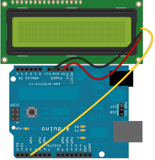
| Serial LCD Kit | Arduino |
|---|---|
| 5V | 5V |
| GND | GND |
| RX | D3 |
Software:
Hello, World: Sending Characters to the Display
Here's a simple example sketch, which uses the SoftwareSerial library (which is included with recent versions of Arduino) to instill our Arduino with more than just the one, hardware, serial port. Now we can use the hardware serial port to listen to the serial monitor, and the second serial port can be used to talk to the LCD.
Here's the code:
#include <SoftwareSerial.h>

SoftwareSerial lcd(2, 3);

void setup()
{
  Serial.begin(9600);  // start serial monitor serial
  lcd.begin(9600);  // start lcd serial
}

void loop()
{
  while(Serial.available())  // If serial data is available do this
    lcd.print((char) Serial.read());
}
Now, plug in your Arduino and upload the code. Open up the serial monitor, and make sure it's set to 9600. Type “Hello, world” into the serial monitor and send it over to the Arduino. The LCD should echo your greeting. Take the LCD for a test drive, discover all the characters it can display!
Clearing the Display, and Other Commands
You'll quickly notice, that the code is severely lacking any sort of clear display command, but don't think for a second that the Serial LCD Kit doesn't have a clear display command. It's got commands up the wazoo! The Serial LCD Kit is set up to accept commands that control the backlight, baud rate, and all sorts of display functionality, like clearing the screen. Have a look at the Kit's “datasheet”, which lists all of the characters and commands you can send to the display. I wrote that, but I understand if it's all gobbledygook to you right now.
The commands are divided into three groups: backlight, baud rate, and special commands. Each command requires that you send at least two bytes to the display. For instance to set the backlight, you first have to send the backlight control byte (0x80, or decimal 128) followed by a byte with any value from 0 to 255. Sending a 0 will turn the backlight completely off, 255 will turn it all the way on, 127 will set it to about 50%, and so on. The backlight setting is stored in the Serial LCD Kit's memory and will be restored when the LCD is turned off and on.
What we really care about right now, though, is clearing the display, which requires a special command. To issue a special command to the LCD, you first have to send 0xFE (or decimal 254) which tells the display to go into special command mode, and wait for a data byte. The clear display command is 0x01 (or decimal 1), that command should be sent immediately after sending the special command byte. So to clear the display we need to send two bytes: 254 (0xFE) followed by 1 (0x01). Check out the datasheet link for all of the special commands. You can do all sorts of fun stuff: scroll the display, turn it on/off and control the cursor.
Our next piece of example code, Serial_LCD_Kit_Clock, delves into sending special commands to the LCD with an Arduino. There are individual functions that clear the display (clearDisplay()), set the backlight (setBacklight(byte brightness)), and set the cursor (setLCDCursor(byte cursor_position)), feel free to copy these and add them to any code you'd like.
The code sets up a digital clock. If you want it to be accurate, you have to set the time in the variables above before uploading the code to the Arduino. The same hookup as before should do.
#include <SoftwareSerial.h>

SoftwareSerial lcd(2, 3);  // This is required, to start an instance of an LCD
int year = 11;  // Enter the current year here, 11 = 2011
int month = 6;  // Enter the current month here, 6 = June
int date = 20;  // Enter the current date here
int day = 1;  // 0 = Sunday, 6 = Saturday
int hours = 23;  // Enter the hours here
int minutes = 59;  // Enter the minutes here
int seconds = 50;  // Enter the seconds here

void setup()
{
  lcd.begin(9600);  // Start the LCD at 9600 baud
  clearDisplay();  // Clear the display
  setLCDCursor(2);  // Set cursor to the 3rd spot, 1st line
  lcd.print("Hello, world");
  setLCDCursor(16);  // Set the cursor to the beginning of the 2nd line
  lcd.print("Running clock...");

  // Flash the backlight:
  for (int i=0; i<3; i++)
  {
    setBacklight(0);
    delay(250);
    setBacklight(255);
    delay(250);
  }
}

void loop()
{
  if (!(millis() % 1000))  // If it's been 1 second
  {
    checkTime();  // this function increases the time and date if necessary
    clearDisplay();  // Clear the display
    setLCDCursor(1);  // set cursor to 2nd spot, 1st row
    printDay();  // print the day
    lcd.print(" ");
    lcd.print(month);  // print the date:
    lcd.print("/");
    lcd.print(date);
    lcd.print("/");
    lcd.print(year);

    setLCDCursor(20);  // set the cursor to the 5th spot, 2nd row
    lcd.print(hours);  // print the time:
    lcd.print(":");
    lcd.print(minutes);
    lcd.print(":");
    lcd.print(seconds);
  }
}

void setBacklight(byte brightness)
{
  lcd.write(0x80);  // send the backlight command
  lcd.write(brightness);  // send the brightness value
}

void clearDisplay()
{
  lcd.write(0xFE);  // send the special command
  lcd.write(0x01);  // send the clear screen command
}

void setLCDCursor(byte cursor_position)
{
  lcd.write(0xFE);  // send the special command
  lcd.write(0x80);  // send the set cursor command
  lcd.write(cursor_position);  // send the cursor position
}

void printDay()
{
  switch(day)
  {
    case 0:
      lcd.print("Sun.");
      break;
    case 1:
      lcd.print("Mon.");
      break;
    case 2:
      lcd.print("Tue.");
      break;
    case 3:
      lcd.print("Wed.");
      break;
    case 4:
      lcd.print("Thur.");
      break;
    case 5:
      lcd.print("Fri.");
      break;
    case 6:
      lcd.print("Sat.");
      break;
  }
}

void checkTime()
{
  seconds++;  // increase seconds
  if (seconds == 60)  // If it's been a minute
  {
    seconds = 0;  // start over seconds
    minutes++;  // Increase minutes
    if (minutes == 60)  // If it's been an hour
    {
      minutes = 0;  // start over minutes
      hours++;  // increase hours
      if (hours == 24)  // If it's been a day
      {
        hours = 0;  // start the day over
        day++;  // increase the day
        if (day == 7)  // if it's been a week
          day = 0;  // start the week over
        date++;  // increase the date
        checkDate();  // this function increases the date/month/year if necessary
      }
    }
  }
}

void checkDate()
{
  // 30 days has sept. apr. jun. and nov.
  if (((month == 9)||(month == 4)||(month == 6)||(month == 11))&&
      (date > 30))
  {
    date = 1;
    month++;
  }
  else if ((month == 2)&&(date > 28))
  {
    date = 1;
    month++;
  }
  else if (date > 31)
  {
    date = 1;
    month++;
    if (month > 12)
    {
      month = 1;
      year++;  // happy new year!
      clearDisplay();
      lcd.print("Happy New Year!");
      delay(5000);
      seconds+=5;
    }
  }
}
This is a good start, but there's plenty of room for growth. Try adjusting the brightness of the display based on what time it was. Make it the brightest at midnight, dimmest at noon. What else can you do with the code?
Now then, that should be enough to get you on your way to using the Serial LCD Kit with a serial interface. If you're happy with that, and don't want your mind blown, I suggest you stop reading here.
Extra Credit: It's More Than a Serial LCD...
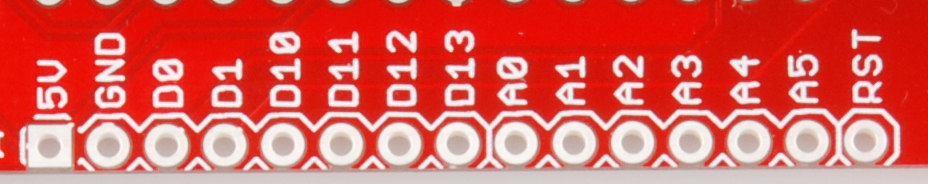
Oh, you've taken the red pill? Well then you get to learn the Serial LCD Kit's very deep, dark secret. It may not look anything like one, but the LCD Kit is actually Arduino-compatible. It has an ATmega328, just like the Arduino, and that ATmega328 has a serial bootloader, just like an Arduino. It can be programmed via a USB-to-Serial board. This means you can hook up all sorts of sensors, blinkies and other I/O to the Kit itself, while continuing to use the LCD to display any info you'd like. The 6-pin serial programming port on the right hand side of the PCB can be connected to an FTDI Basic Breakout.
You may want to solder some right-angle male headers in the Serial LCD to get a good connection between the two.
With the FTDI board connected, and Arduino open, simply select the corresponding COM port in the Tools>Serial Port menu, and select Arduino Duemilanove or Nano w/ ATmega328 under the Tools>Boards menu. Though it probably won't look like it's doing anything, try uploading Blink, change the LED pin to 9 to at least see the backlight of the LCD flick on and off. Remember, you can download the Serial LCD Kit firmware here. If you ever want to turn it back into a Serial LCD, upload it to the LCD like you would any sketch.
If you want to be really adventurous, and get the most out of the Serial LCD Kit, I'd recommend first taking a trip over to where the Serial LCD Kit's source code is hosted and getting a good idea how the code works. That firmware is written as an Arduino sketch, and uses a great little Arduino library named LiquidCrystal to control the LCD. The LiquidCrystal library makes controlling the LCD with an Arduino super-simple.
You should also get a good feeling for the kit's schematic. There are a few Arduino pins that can only be used with the LCD (4-9), but pins 10-13, and all of the analog pins can be used with any device you'd normally connect to an Arduino. The available pins are all broken out on the bottom of the PCB.
The expansion header: all extra pins of the ATmega328 are broken out here
Remember, this part is all very extracurricular. Don't feel at all required to use your Serial LCD Kit as an Arduino. I just wanted to let you know what's possible with this kit.
Resources:
- Serial LCD Kit Schematic
- Serial LCD Kit Firmware (github)
- Serial LCD Kit Command List (github wiki)
- NewSoftSerial Library - Required for the example sketches. Sets up a second (third, fourth,...) serial port on the Arduino.
- Serial LCD Kit Passthrough Example Sketch - Send any character from the Arduino's serial monitor to the LCD.
- Serial LCD Clock Example Sketch - Displays a digital clock on the Serial LCD. This is a good example of how to use special commands, like clear, with the display.
Conclusion:
Now I'll leave you and your Serial LCD Kit in peace. I hope you've learned a good amount about the display. I also hope you're left with questions and ideas about what you're going to do with it next. If you've still got questions about the display, or comments about the tutorial, please drop them in the comments box below or email us.
where exactly do the 3 wires: the yellow, red, and black attach to the LCD board?
Hey Thanks for all the info and resources, I was able to build this thing without any trouble, the one hang up I'm still trying to figure out is when I upload a code using the unit as an Arduino what is the change on the code I need make to enable the screen? I imagine all the pins that are not available have to be addressed to make the display work, correct? Thanks in advance!
Well, turns out the baud rate somehow slipped to 4800, and the transmit pit is pin 4 of J1, not pin 2 or 3, as the documentation for the USART example from ATMEL states. Works OK! Fred
Hi, tried to hook up the LCD kit to an ATMEL Xmega A3Bu board, using the USART example; compiled and programmed no problem. Can't get the LCD to display what I tell it to. Using USARTC0, and the yellow wire to either Pin2 or 3 of J1.
Thanks in advancce,Fred
Hi, when I was working on my lcd, its backlight went off suddenly. before that happened, some non-readable chars appeared (possibly my fault with memory things), then I got lack of backlight. I can still read characters, but it is very hard without backlight. I think it is not related with backlight command (0x80 brightness). any idea?
My backlight started to act funny too when I used code from just the LCD library. I think it has something to do with it not controlling the led. But, I had to upload code from something that used the backlight like the voltmeter example and the backlight came back on. I'm by far no expert at this but that's what I did to fix it. Hope it helps.
So... I bought this thing and I'm confused on what to do with it. I got it all put together and after about four hours finally got something to show on the screen. I soldered a IC socket on and didn't realize that I have to have the IC in there for it to work. Yeah I know.....but, because in the few paragraphs above "you don't have to use it as an arduino". Anyway, I put in the IC and I was amazed something showed up, sweet. So, here's the confusing part for me, why do I have to have the atmega chip in the LCD and also a atmega chip in the arduino? I don't have a FTDI Breakout just yet, but I'm getting on soon, I'm thinking that if I want to use it as a clock I would want the LCD to be programmed with the sketch and all of the other things to make it work. Because you definitely can't upload code to any atmega 328 and slap it into the LCD and expect it to work. So if anyone has any info that could help me that would be awesome, sorry for the rambling on.
Hi, I'm hoping someone can help me with this. I set up all the parts and soldered everything as mentioned above. However, when I upload the first basic code to display the "Hello, world", absolutely nothing happens. The kit is connected to the arduino (red wire in 5V, black wire in GND and yellow wire in digital 3). I see that there is light in the actual LCD, however, there is no message. Could it be that the library/code have changed since this tutorial was written? I really hope someone can guide me to solve this issue. Thanks!
Check the contrast on your potentiometer and make sure all of your soldered connections are good and clean. Loose connections can really cause problems with these screens. Also, make sure you have a good connection between the yellow wire and your Arduino pin. The SoftwareSerial library is still up to date on Arduino, so that shouldn't be an issue for you. If you are still having trouble with this, please contact techsupport@sparkfun and they should be able to help you out further.
I'm not able to change the baud rate in this kit. Can anyone please tell me how to do that I tried what was told to do in datasheet: void setBaud() { lcd.write(0x81); // send the baud rate control byte lcd.write(2); // send the data byte. } but no use. Need help. Please !
Since the clock worked I moved on to use the FTDI breakout and soldered a male header to the serial board. In checking which way to plug in the FTDI breakout I noticed that the pin sequence did not match. Serial board: DTR, TX0, RX1, 5V, GND, GND FTDI board: DTR, RX1, TX0, 3V3, CTS, GND Is this simply transmit connected to receive and vice versa? And what about 5 volts to 3? volts? Dave
I tried the clock example and the code uploaded but it displayed an error: avrdude: stk500_getsync(): not insync: resp=0x00 What does it mean?
Generally this means you have the wrong board type selected, or your board isn't connecting to the computer properly. Double check your wiring and soldering points and if you are still having trouble, contact tech support and they'll be able to assist you further.
Thanks to all who submitted fixes to make the example code functional with the SoftwareSerial library! The tutorials been updated to use that instead of NewSoftSerial.
Pardon Me but wats the commands to set the lcd sizes? i used a 4x16 and its set to 2x20.
The code below was fixed as you suggested by replacing "NewSoftSerial" with "SoftwareSerial". The code does compile but when I tried to Upload, it sends me a message of
"avrdude: stk500_getsync(): not in sync: resp=0x00"
I'm wondering what does this message mean? Therefore, I think this prevent me from sending new message in SerialMonitor. Please advice. Thanks ahead.
include
SoftwareSerial lcd(2, 3);
void setup() { Serial.begin(9600); // start serial monitor serial lcd.begin(9600); // start lcd serial }
void loop() { while(Serial.available()) // If serial data is available do this lcd.print((char) Serial.read()); }
I'm getting the same error, although I'm trying to upload a different program. Any chance you figured out how to fix it?
As of Arduino 1.0, NewSoftSerial is an officially supported software serial library. To make the above code work, simply change all NewSoftSerial references to SoftwareSerial.
Also in Arduino 1.0, the 'BYTE' keyword is no longer supported. This change will prevent the Serial_LCD_Kit_Clock.pde code from working correctly.
To get the Serial_LCD_Kit_Clock.pde code to work correctly with Arduino 1.0, replace the 'setBacklight()' 'clearDisplay()' and 'setLCDCursor()' functions with the following:
Thanks for posting that code update, I am new and it really helped out.