GPS Shield Hookup Guide
 a_cavis
Introduction
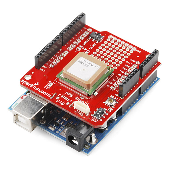
The SparkFun GPS shield has several convenient features that make it easy to use GPS modules with the Arduino Uno and SparkFun RedBoard (or any development board that supports the Arduino shield form factor).
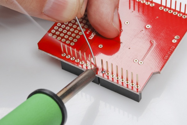
Assembly
Before use, you will need to solder headers to your shield. Take a look at the Shield Assembly tutorial if you need a refresher. The GPS Shield uses the Uno R1 footprint with 2x 8-pin and 2x 6-pin headers.
Required Materials
The GPS Shield Kit comes with the shield, headers, an EM-506 GPS module and foam tape for attaching the module to the shield.
If you purchased the GPS shield separately, you will need to acquire a GPS Module of your choice as well as the corresponding cables, headers or other connectors.
Suggested Reading
If you haven't worked with GPS before, you may want to read the following tutorials before continuing with the GPS Shield.
- GPS Basics - If you've always wanted to know how GPS works, this is the tutorial for you.
If you're not using Arduino or another microcontroller, you can still view the GPS module's serial output (and send commands to the GPS) using a terminal program.
Shield Overview
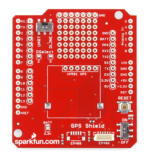
The top of the GPS shield:
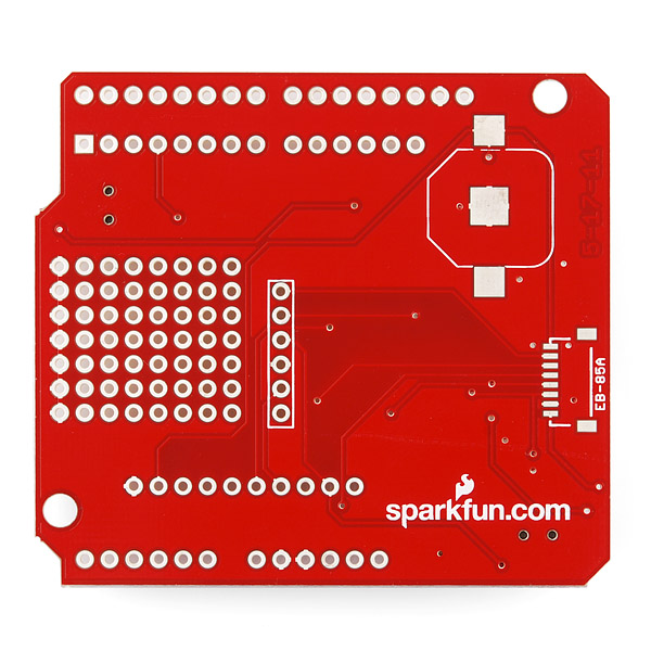
and the bottom:
The SparkFun GPS Shield includes a 6-pin JST-SH socket (labeled EM406 on the top) that fits both the EM-506 (included with the GPS shield kit) and its discontinued predecessor the EM-406A as well as the the GP-635T. There are exposed pins and a small prototyping area for use with other GPS modules. And there are unpopulated pads for the 5-pin JST-SH connector found on the discontinued EM-408 module (labeled EM408 on the top) .
The UART/DLINE switch connects the GPS module's serial lines to either Arduino hardware serial (D0/RX and D1/TX) or a user-selectable pair of software serial pins (D2 and D3 by default).
The closed solder jumpers marked Dselect 2 and 3 determine which pins are used in DLINE mode.
The ON/OFF switch controls power to the GPS module. The RESET button connects to the Arduino underneath.
On the back of the shield, there is an unpopulated 12mm coin cell battery holder footprint for adding battery backup and warm start capabilities.
There is an additional unpopulated footprint for an 8-pin JST-SH connector as seen on the discontinued 85A GPS module.
The BATT/3.3V jumper connects the VBAT lines on the unpopulated JST connectors to either the (unpopulated) backup battery or to the Arduino's 3.3V line. 3.3V is selected by default.
Code Example
For this example, you will need to install the TinyGPSPlus library. Take a look at our Arduino library install tutorial if you've never installed an Arduino library before.
Mikal Hart's Arduiniana.org has a full overview of all of the capabilities of the TinyGPS++ library, but the most important one is parsing the GPS module's NMEA sentence output into latitude and longitude.
Press your completed Arduino shield (with headers soldered and your GPS plugged in or soldered on) onto your Arduino, and connect your Arduino to your computer with your USB cable.
You will be using software serial for this example, so leave the switch in DLINE.
Upload the example sketch below to your Arduino.
language:c
#include <TinyGPS++.h>
#include <SoftwareSerial.h>
/*
 This example uses software serial and the TinyGPS++ library by Mikal Hart
 Based on TinyGPSPlus/DeviceExample.ino by Mikal Hart
 Modified by acavis
*/

// Choose two Arduino pins to use for software serial
// The GPS Shield uses D2 and D3 by default when in DLINE mode
int RXPin = 2;
int TXPin = 3;

// The Skytaq EM-506 GPS module included in the GPS Shield Kit
// uses 4800 baud by default
int GPSBaud = 4800;

// Create a TinyGPS++ object called "gps"
TinyGPSPlus gps;

// Create a software serial port called "gpsSerial"
SoftwareSerial gpsSerial(RXPin, TXPin);

void setup()
{
  // Start the Arduino hardware serial port at 9600 baud
  Serial.begin(9600);

  // Start the software serial port at the GPS's default baud
  gpsSerial.begin(GPSBaud);

  Serial.println(F("DeviceExample.ino"));
  Serial.println(F("A simple demonstration of TinyGPS++ with an attached GPS module"));
  Serial.print(F("Testing TinyGPS++ library v. ")); Serial.println(TinyGPSPlus::libraryVersion());
  Serial.println(F("by Mikal Hart"));
  Serial.println();
}

void loop()
{
  // This sketch displays information every time a new sentence is correctly encoded.
  while (gpsSerial.available() > 0)
    if (gps.encode(gpsSerial.read()))
      displayInfo();

  // If 5000 milliseconds pass and there are no characters coming in
  // over the software serial port, show a "No GPS detected" error
  if (millis() > 5000 && gps.charsProcessed() < 10)
  {
    Serial.println(F("No GPS detected"));
    while(true);
  }
}

void displayInfo()
{
  Serial.print(F("Location: "));
  if (gps.location.isValid())
  {
    Serial.print(gps.location.lat(), 6);
    Serial.print(F(","));
    Serial.print(gps.location.lng(), 6);
  }
  else
  {
    Serial.print(F("INVALID"));
  }

  Serial.print(F("  Date/Time: "));
  if (gps.date.isValid())
  {
    Serial.print(gps.date.month());
    Serial.print(F("/"));
    Serial.print(gps.date.day());
    Serial.print(F("/"));
    Serial.print(gps.date.year());
  }
  else
  {
    Serial.print(F("INVALID"));
  }

  Serial.print(F(" "));
  if (gps.time.isValid())
  {
    if (gps.time.hour() < 10) Serial.print(F("0"));
    Serial.print(gps.time.hour());
    Serial.print(F(":"));
    if (gps.time.minute() < 10) Serial.print(F("0"));
    Serial.print(gps.time.minute());
    Serial.print(F(":"));
    if (gps.time.second() < 10) Serial.print(F("0"));
    Serial.print(gps.time.second());
    Serial.print(F("."));
    if (gps.time.centisecond() < 10) Serial.print(F("0"));
    Serial.print(gps.time.centisecond());
  }
  else
  {
    Serial.print(F("INVALID"));
  }

  Serial.println();
}
Open your Arduino serial terminal by going to Tools > Serial Monitor
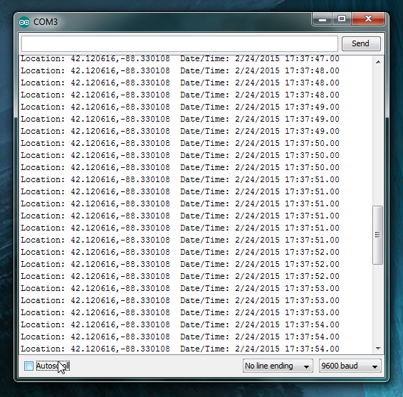
Latitude, longitude, and time stamp values should be streaming by! You'll never get lost in front of your computer again!
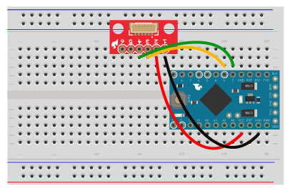
Using the GPS Breakout
If you are using a smaller Arduino like the Pro Mini you can use a GPS Breakout instead of the GPS shield, though your selection of compatible modules is smaller than it is with the shield.
Troubleshooting
"No GPS Detected" error
If you're using the EM-506 GPS from the GPS Shield Kit, make sure the JST-SH cable is firmly seated on both the module side and on the shield's socket.
Check that the serial select switch is in DLINE
Check that the shield's power switch is ON
If you're using an Arduino based on a chip other than the ATMega328, make sure you are using a pair of software-serial compatible pins.
"INVALID" location, date, and time
Location: INVALID Date/Time: INVALID INVALID
Give your GPS some time to get a fix. The EM-506 module shows a solid red light for no fix and flashes when the fix is successful.
If your module fails to get a fix after several minutes, try moving closer to a window or even outside. In severe cases, such as in an urban canyon or inside a building with heavy concrete floors and ceilings, you may have to completely change locations.
Resources and Going Further
Check out these other GPS related tutorials.
- Alphanumeric GPS Wall Clock Harness the time signal from your GPS module to make a wall clock you never have to set!
- Weather Shield Hookup Guide GPS adds location and time data to your personal weather station
- GPS Tracking Comparison Satellite cluster in the sky, which module's the fairest on the fly?