
The Rotary Keyboard
A Revolutionary New Input Device?
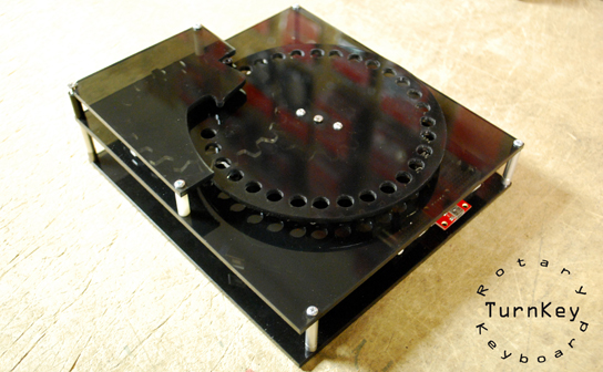
Always on the cutting edge, the time has come for SparkFun to completely change the way that you think about text input. Okay, so when I said revolutionary I guess I meant less "radically new and innovative" and more, you know... revolving. But man does this thing revolve! Aside from being just a seriously asinine peripheral, the rotary keyboard (nicknamed "TurnKey") is actually a good demonstration of why you might want to hack a servo.
Hack A Servo? Why?
Your standard hobby servo will generally communicate in one direction. You give it a position to move to, it moves to that position, end of conversation. But the closed system inside the servo knows what position it's in somehow, right? Why can't we get access to that information? Well in some situations a servo can be assumed to be in the last place you told it to go. If that's the case, you can simply call the servo.read() function which gives you the value of the last servo.write() function. But what if that servo has moved since then? Your system has no way of finding out where a servo has been moved to unless it was the system doing the moving. But there's a simple hack that can fix that problem, just tie into the sensor that tells the servo controller where it is. Servos use potentiometers to detect their position so all you really need to do is tie into the center of the servo potentiometer and read it with one of your analog pins!
Why is this important to the rotary keyboard? Well because it allows us to cheat! See, inside of an actual dial like you might find on an old phone, there is a mechanism that returns the dial to its home position between dials. In the process of returning to the home position, the dial produces a certain number of 'clicks' which are decoded into the appropriate numbers. An appropriately hacked servo can fake that action by allowing us to dial a number (or letter), detecting the end of the dial, then returning back to home without the use of complicated spring mechanisms. We won't get away from mechanics completely, however, because the range of our servo is only 180 degrees and we'll need to gear it down to get a full rotation out of it. But we can take care of that after we've hacked our servo, let's get to work.
Let's Do it Then!
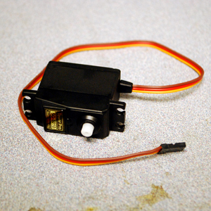
Here's our victim. This is our Large Servo, as you can see it has the standard 3-wire servo cable: Ground, Vcc and Signal. We need to throw another wire on this thing if we want to read the potentiometer so let's open it up and see if we can find something that looks like a pot footprint.
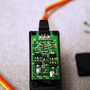
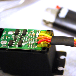
Now that looks promising, just below the 3-pin header where the servo leads connect there's another 3-pin footprint. I don't have a picture, but if you lift the board just slightly, you can actually see the potentiometer leads connecting on the other side. The trick to this is that all you really need is a wire connected to the wiper on the potentiometer, but I have a nice 3-wire connector and, who knows, maybe I'll want to use this servo as just a geared potentiometer some day. So I slapped my 3-wire connector on the the 3-pin potentiometer footprint, added some tape to avoid a nasty short with the servo leads and a little bit of heatshrink tubing to class the whole thing up. This is what it should will probably look like when you've hacked it:
It's a thing of beauty, now you can screw the case back together and show off your mutant servo. And now that we have our servo properly modified, it's time to fabricate the dial and board for our rotary keyboard. Now because the servo is only a half-rotation servo, I'll need to gear it down to use it as a rotary dial. I decided to cut a pair of really simple gears on the laser cutter with a 1:2 ratio, that way I'll get just about a full 360 out of it. I'm not going to go too much into the mechanical build for this, but it's probably for the best. This thing is pretty much cobbled together, my only saving grace was the laser cutter. Here's the top board and dial all assembled, this is basically the working portion of the thing. As you can see, all 26 letters of the alphabet are etched underneath the dial as well as period and space. You'll need a number pad (or accompanying number-wheel) if you want to do any kind of serious rotary word processing. Don't mind the fingerprints, this smokey acrylic looks great but only if you don't ever touch it. lesson learned.
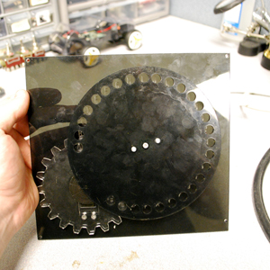
There's an accompanying base-plate that everything bolts down to but that's only for the sake of stability. One thing that will be added before the end, however, is something called a "finger stop," which is the part that you dial to.
Wiring and Code
I think it's time to look at the Arduino side of things. Like I said, this is supposed to work like a USB keyboard which means that it needs to enumerate using the USB-HID protocol. There are a couple of different ways to do this. In fact, Jim wrote an excellent tutorial on using the Pro Micro's USB capabilities to make your own keyboard. For this project, however, I'm using a Duemilanove that I happened to have laying around so the Pro Micro method is out. Luckily, Practical Arduino has a great library for using your Arduino as a virtual USB keyboard, in order to use the library we will have to put together a simple circuit that lets our 5V system communicate with the 3V(ish) USB port. They use current limiting resistors and a pair of 3.6V Zener diodes to clamp the signaling voltage around where the USB wants it. I'm told, however, by someone who actually has a degree in this stuff that it's not clamping hard and that the signaling voltage may be even slightly higher than the USB port would like to see. I've used this circuit for a long time with no problems, but it's entirely possible that I've dramatically shortened the life of my USB hardware as well. Here's what my hardware looks like after some finoodling around.
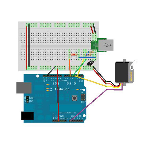
As you can probably see, I've connected everything the way you might expect. The USB Keyboard hardware is part-for-part just like the example diagram on the Practical Arduino page; the servo is connected to power and ground with signal at pin 3 and the potentiometer tap is wired to pin A0. Make sure you watch your polarity on those diodes!
I put all of this together on a breadboard and then stuffed it into the keyboard, I also added the finger stop so it could be accurately dialed and went on to program it. I'll go ahead and show you the code with the comments now and then try to explain myself after you've seen it.
/*
Rotary Keyboard
written by N.Poole
SparkFun Electronics 2012

This code is released as Apathyware:
"The code doesn't care what you do with it, and neither do I."

This demo code was written for the Rotary Keyboard tutorial which can
be found at: http://www.sparkfun.com/tutorials/351

*/

#include <Servo.h>
#include "UsbKeyboard.h" //This is the USBKeyboard library from the Practical Arduino site.

Servo myservo; //Here's our servo
int val; //This is a variable we'll use later
int last; //This is a variable we'll use later

//The following variables all have to do with the fact that the USBKeyboard.update() method
//needs to be called once every couple... I'm not really sure actually, but it needs to be
//called occasionally for things to run smoothly. I used a system of "clocks and flags" to
//keep track of tasks inside the routine without neglecting to ".update()"

int clock1; //Servo reset "clock"
int clock2; //Dial Hold "clock"
boolean flag1 = 0; //"A letter's been dialed" flag
boolean flag2 = 0; //"Let's not send the same command 1000 times" flag

#define BYPASS_TIMER_ISR 1
//This is an option from the USBKeyboard library which appears to disable Timer0. Without
//this being TRUE, this library doesn't work nearly as well.

void setup() {

#if BYPASS_TIMER_ISR //Here's where the switch above messes with the timer.

  TIMSK0&=!(1«TOIE0); //The double waka here will need to be re-typed if you
#endif                //paste this into Arduino. I used a special character because
                      //of formatting issues.
myservo.attach(3); //And here we attach our servo

}

#if BYPASS_TIMER_ISR //And I'm no rocket surgeon but I think this is a replacement
                     //for delay that kicks in when you disable the timer... I
                     //could be wrong. Probably am!
void delayMs(unsigned int ms) {
   /*
  */
  for (int i = 0; i < ms; i++) {
    delayMicroseconds(1000);
  }
}
#endif

void loop()  //Ah, the meat of the code
{

  UsbKeyboard.update(); //This is that annoying method that you need to call every now and then

//The "if" statements below that test clock1 are my replacement for delay. Instead of stopping
//everything. These statements execute commands in order while allowing the ATMega to take care
//of USBKeyboard.update()

  if(clock1 < 10000 && flag2==0){ //Return the servo to home, the flag keeps it from repeating
  myservo.write(0); flag2=1;}
  if(clock1==10000){
  myservo.detach();} //After it's had time to get back, detach it. Now we can move it by hand.

  if(analogRead(A0)>180 && clock1>12000){ //After you've reset and detached the servo, look for
                                          //an analog value above home position.
while(flag1==0){ //This flag flips when we get a letter
    UsbKeyboard.update(); //Since we'll be here a while we'd better find USBKeyboard.update() a place to sit.
    val = analogRead(A0); //Read the Potentiometer tap to see where the dial is.
    if(val==last && clock2>2500){Translate();}; //Make sure we're not still moving it, if not then read it.
    if(clock2==1){last = val;}//At the beginning of each clock2 cycle, save our last pot value for comparison
    if(clock2>2500){clock2=0;}//Restart clock2 every 2500 cycles
    clock2++;//Tick Tock
  }

clock2 = 0; //If you're here, you're finished with this clock and it needs to be reset

}


if(clock1<32000){clock1++;} //don't let the clock roll over
if(flag1==1){flag1 = 0; clock1 = 0; flag2 = 0;} //if you've sent a letter, reset all of our flags and clocks and start over
}

void Translate(){ //This function "translates" our potentiometer value into a letter of the alphabet

int lettr = map(analogRead(A0),189,521,27,0); //map the range from 'A' to 'SPACE' to the values 1 - 27

switch (lettr){ //Here's the boring part, just telling the USBKeyboard.sendKeyStroke() method which keystroke to send

  case 1:
  UsbKeyboard.sendKeyStroke(KEY_A);
  break;

  case 2:
  UsbKeyboard.sendKeyStroke(KEY_B);
  break;

  case 3:
  UsbKeyboard.sendKeyStroke(KEY_C);
  break;

  case 4:
  UsbKeyboard.sendKeyStroke(KEY_D);
  break;

  case 5:
  UsbKeyboard.sendKeyStroke(KEY_E);
  break;

  case 6:
  UsbKeyboard.sendKeyStroke(KEY_F);
  break;

  case 7:
  UsbKeyboard.sendKeyStroke(KEY_G);
  break;

  case 8:
  UsbKeyboard.sendKeyStroke(KEY_H);
  break;

  case 9:
  UsbKeyboard.sendKeyStroke(KEY_I);
  break;

  case 10:
  UsbKeyboard.sendKeyStroke(KEY_J);
  break;

  case 11:
  UsbKeyboard.sendKeyStroke(KEY_K);
  break;

  case 12:
  UsbKeyboard.sendKeyStroke(KEY_L);
  break;

  case 13:
  UsbKeyboard.sendKeyStroke(KEY_M);
  break;

  case 14:
  UsbKeyboard.sendKeyStroke(KEY_N);
  break;

  case 15:
  UsbKeyboard.sendKeyStroke(KEY_O);
  break;

  case 16:
  UsbKeyboard.sendKeyStroke(KEY_P);
  break;

  case 17:
  UsbKeyboard.sendKeyStroke(KEY_Q);
  break;

  case 18:
  UsbKeyboard.sendKeyStroke(KEY_R);
  break;

  case 19:
  UsbKeyboard.sendKeyStroke(KEY_S);
  break;

  case 20:
  UsbKeyboard.sendKeyStroke(KEY_T);
  break;

  case 21:
  UsbKeyboard.sendKeyStroke(KEY_U);
  break;

  case 22:
  UsbKeyboard.sendKeyStroke(KEY_V);
  break;

  case 23:
  UsbKeyboard.sendKeyStroke(KEY_W);
  break;

  case 24:
  UsbKeyboard.sendKeyStroke(KEY_X);
  break;

  case 25:
  UsbKeyboard.sendKeyStroke(KEY_Y);
  break;

  case 26:
  UsbKeyboard.sendKeyStroke(KEY_Z);
  break;

  case 27:
  UsbKeyboard.sendKeyStroke(KEY_SPACE);
  break;
}

#if BYPASS_TIMER_ISR  // Figure out how much delay this thing needs (from USBKeyboard example)
    delayMs(20);
#else
    delay(150);
#endif

 myservo.attach(3); //re-attach our servo so it can return to home

flag1=1; //set the "A letter's been dialed" flag
}
So, let's see if I can explain this code in terms of the order of execution. When you plug in the keyboard, the USBKeyboard library starts a connection to the computer. The only way to make this connection is to continue to call USBKeyboard.update() so we need to set up our program in such a way that we won't stop everything for any extended period of time, leaving USBKeyboard.update() unattended. On top of that, between the servo and the USB interface, there aren't any timers left over to make it easier. What I end up doing in the code above is "timing" all of the steps in my code based on a few "clocks" which are really just iteration counters.
So after all of my clocks and flags are set, the code dumps out into the main loop. The first order of business there is to send our servo home. On the first iteration it tells the servo to go home, then for the next 9999 iterations or about a second (I know, right?) it skips everything except for update and clock iteration. This gives the servo time to get home because after 10000 iterations, we detach it so that we can actually move the dial. Now we give the potentiometer tap 2000 iterations to settle because the readings jump all around when the servo is attached, I pulled the 2000 number out of thin air as a short delay.
After that short delay we start looking for the potentiometer value to move above the "home" position of the dial. Our clock1 will run out in this time so after 32000 iterations we stop it. If the dial is moved, we start a second clock, which runs on a cycle and starts looking for the dialing to finish. The challenge now is determining when the dial isn't being moved anymore. This is done by sampling the analog pin every 2500 iterations of the while() loop and comparing it to the previous sample. When two samples are the same, that means you've left the dial alone for a few milliseconds and the servo can take over again.
Before the servo takes over, a number between 1 and 27 is generated based on the position of the potentiometer. That number is used to determine which keystroke to send using the USBKeyboard library. After we've sent the correct keystroke, we re-attach the servo so that it can return home and we set a flag to get out of the dial sampling loop. Once we're free of the dial-sampling loop, we reset clock2 since we won't be needing it until next time around and then we reset everything else and get bumped right back to the beginning.
Conclusion
Easy Cheesy, Huh? I know, not really.
Well how about a laugh to take your mind off things then? I decided to take my sweet new keyboard and put it through its paces using an online typing test. It was one of the most frustrating experiences I can remember. Besides not having any caps control, punctuation or numbers, the rotary keyboard is also incapable of generating text at faster than 1 character per 1.5 seconds. As you can see, I didn't fare well:
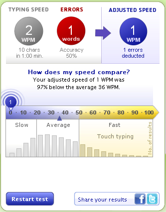
Success! Okay, so it isn't the fastest thing in the world but it sure looks cool. In any case, if it ends up on the next iPad just remember you saw it here first!
Happy Hacking!
Re-posting from YouTube to here:
Maybe not all that efficient for individual characters, but how about as a giant pre-programmed/programmable "clip board"? Name, full name, email, street address, home lat/long, URL's, etc. as different positions? Perhaps not that useful in the grand scheme of things, but given you already have one then perhaps more useful.
Rotary clipboard access... I like it.