
PG3B ICProg tutorial

Update: Now you can use the ever popular and easy to use ICProg! We have updated this tutorial to use ICProg. The original tutorial can still be found here.
Remember! There is support on the SFE Support Forum!
You've got your programmer. You've got your PIC. It's time to get burning.
This tutorial will cover the software setup and various chip locations using the PG3B programmer. Getting your programmer to work for the first time can be frustrating and time consuming. We wrote this tutorial to try to expedite things. And, look at the bright side - Once you get your setup correct, you should be able to program without every having to mess with it again!
Warning: Never insert or remove a PIC from the PG3B while the programmer is in program mode. Do not send print jobs to the parallel port while you've got the PG3B attached to the parallel port. Fried PICs and fried programmers will result!
The PG3B Parallel programmer. First the basics -
Cable : You will need a 25 Pin conductor parallel cable - Male to Female. This is remotely like a printer cable, but with a 25 Pin connector in place of the Printer Port connector. Make sure you get a cable with all 25 pins connected.
Power : The board must be powered with 15V-18V DC power supply. The current is not that important. >100mA should do. The main thing is the voltage. If your power supply is just barely 15V, under load, it will more likely be 13-14V. This is very bad.
For PICs to program, the MCLR (reset pin) must be raised to about 13V. If you do not reach this level - say 10.5-11.5V, programming will be very hit-or-miss. If you get a 16F628 that came from a nice clean part of the big wafer, it will go into program mode just fine at 10V. If you get a normal chip like the rest of us, you will want to make sure you get that MCLR pin to 12-13V to make sure the PIC goes into program mode.
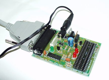
Cables Attached
Software : Use ICProg! Why? Because it programs the greatest number of PICs including the new 16F676, 16F819, and 12F675! Download the zip file and open it. There is only one file (the way all programs should be) - icprog.exe. Store this file somewhere handy like the desktop - you will be using it quite a bit!
Windows NT and XP users! : Click here.
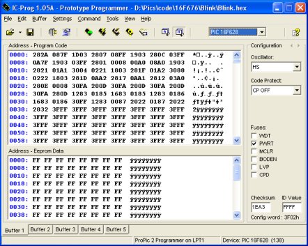
The Main ICProg Window
So you've got the software installed. Now you've got to get it talking to the PG3B. To setup ICProg - under the 'Settings' menu select 'Hardware'.
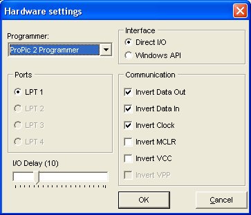
Hardware: Select ProPic 2 Programmer
From here select the ProPic 2 Programmer from the drop down box. You will also need to invert the Data I/O and Clock lines. Everything else should be default. Click 'OK' to close the window.
HEX What?
The Basic ICProg Window
Now open some HEX file to test with. Make sure it's small - you don't really need to fill up the PIC just yet, do you? The HEX file should have the fuses encoded - ICProg will recognize these and select the fuses and oscillator settings for you. You must select the processor by hand. Incorrect processor selection can fry chips! Programming 16F873 is very different from 16F873A!
If you are using the 16F628, you are welcome to download our Blink program (the C code is here). The blink.hex file, when correctly loaded, will turn both PORTA and PORTB (all I/O pins, really) high and low every second. This is very easy to test for if you have a multimeter handy. If you have the PIC-P18 evaluation board, the status LED will blink on and off (assuming jumper J1 is shorted with a jumper).
PIC Locations -
The locations for all the different pin PICs are indicated on the board.
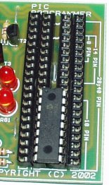
16F628 in the 18Pin PIC Position
You must look very closely but multiple Pin 1 indicators are located in between the 2nd and 3rd sockets. The Pin one indicator for the 28 and 40 pin PICs is the white line between the two sockets at the top of the picture. Pin 1 for the 14 and 8 pin PIC devices is the second line down (seen in the picture). The 18 pin Pin 1 indicator line is the third down (currently covered by the 16F628). You can see the pin 1 'dimple' on the PIC matches to the indicator in between the sockets. For slim PICs - 16F873, F84, F682, etc. the PIC must straddle sockets 2 and 3 as shown in the picture. For larger PICs - 16F877, the PIC must straddle the outer sockets 1 and 4.
Get your PIC located correctly in the socket. Now go back to the ICProg software and hit the button with the lightening bolt. The PG3B will flash the programming LEDs and the PIC should be successfully verified!
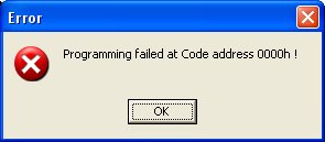
The dreaded generic ICProg error
What to do if you get the message 'Programming failed at Code address 0000h' - This is the generic error code that means something (anything) is wrong.
Make sure that:
-
the parallel cable is plugged into LPT1.
-
the programmer is powered correctly and the power light is on.
-
the PIC is oriented in the socket correctly or - the ICSP cable is attached firmly and correctly to whatever development board you may have.
-
you have selected the correct PIC for your board. Again 16F873 is different from 16F873A.
Now that you've got the socket working, start using the ICSP cable. Take a look at another one of our tutorials titled 'Hook in the Magic' for more information.
Installing the Windows NT/2000/XP Driver -
XP and NT do screwy things with the serial and parallel IO that previous Windows versions did not. This special driver allows you to successfully use your parallel/serial programmer with any Windows machine.
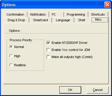
The Options Window
First you will need to download the NT/2000 Driver from the ICProg website downloads page. Put the NT/2000 driver file in the same directory as the ICProg.exe file. In ICProg, click on 'Settings' in the main window and open the 'Options' window. Select the 'Misc' tab. Click 'Enable NT/2000/XP Driver'. ICProg will then restart with the new driver and everything should be peachy.
Dah! -
What to do if you've read through this tutorial twice and you are still having problems.
You may want to checkout the support forum at ICProg. But please post all questions on the SFE Support Forum - we don't want to bug Bonny Gijzen, author of ICProg, with Olimex specific questions.
Email us! We can help!

You've got your programmer. You've got your PIC. It's time to get burning.
This tutorial will cover the software setup and various chip locations using the PG3B programmer. Getting your programmer to work for the first time can be frustrating and time consuming. We wrote this tutorial to try to expedite things. And, look at the bright side - Once you get your setup correct, you should be able to program without every having to mess with it again!
Warning: Never insert or remove a PIC from the PG3B while the programmer is in program mode. Do not send print jobs to the parallel port while you've got the PG3B attached to the parallel port. Fried PICs and fried programmers will result!
The PG3B Parallel programmer. First the basics -
Cable : You will need a 25 Pin conductor parallel cable - Male to Female. This is remotely like a printer cable, but with a 25 Pin connector in place of the Printer Port connector. Make sure you get a cable with all 25 pins connected.
Power : The board must be powered with 15V-18V DC power supply. The current is not that important. >100mA should do. The main thing is the voltage. If your power supply is just barely 15V, under load, it will more likely be 13-14V. This is very bad.
For PICs to program, the MCLR (reset pin) must be raised to about 13V. If you do not reach this level - say 10.5-11.5V, programming will be very hit-or-miss. If you get a 16F628 that came from a nice clean part of the big wafer, it will go into program mode just fine at 10V. If you get a normal chip like the rest of us, you will want to make sure you get that MCLR pin to 12-13V to make sure the PIC goes into program mode.
Cables Attached
Software : Use WinPicProg! It will program the most popular PICs. It has a decent support forum. And it's free! Download the zip file and open it. There is only one file (the way all programs should be) - WinPicProg.exe. Store this file somewhere handy like the desktop - you will be using it quite a bit!
Windows NT and XP users! : If you are running under Windows XP or NT you will need to download the 'port95nt.exe' from the WinPicProg website. XP and NT do screwy things with the serial and parallel IO that older Windows versions did not. Port95NT takes care of all this for you! Run port95nt and allow the install to do its thing.
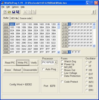
The Basic WinPicProg Window
So you've got the software installed. Now you've got to get it talking to the PG3B. To setup WinPicProg - under the 'Options' menu select 'Hardware'.
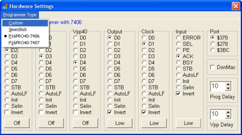
Hardware: Select PIC16PRO40-7406
From here select the P16PRO40-7406 programmer. This will setup the correct pin connections. Don't worry about setting anything else, just click on the 'X' and close the window. WinPicProg should now have the hardware setup correctly.
HEX What?
The Basic WinPicProg Window
Now open some HEX file to test with. Make sure it's small - you don't really need to fill up the PIC just yet, do you? The HEX file should have the fuses encoded - WinPicProg will recognize these and select the fuses and oscillator settings for you. You must select the processor by hand. Incorrect processor selection can fry chips! Programming 16F873 is very different from 16F873A!
If you are using the 16F628, you are welcome to download our Blink program. The blink.hex file, when correctly loaded, will turn Pin 9 of the 16F628, high and low every half second. This is very easy to test for if you have a multimeter handy. If you have the PIC-P18 evaluation board, the status LED will blink on and off (assuming jumper J1 is shorted with a jumper).
PIC Locations -
The locations for all the different pin PICs are indicated on the board.
16F628 in the 18Pin PIC Position
You must look very closely but multiple Pin 1 indicators are located in between the 2nd and 3rd sockets. The Pin one indicator for the 28 and 40 pin PICs is the white line between the two sockets at the top of the picture. Pin 1 for the 14 and 8 pin PIC devices is the second line down (seen in the picture). The 18 pin Pin 1 indicator line is the third down (currently covered by the 16F628). You can see the pin 1 'dimple' on the PIC matches to the indicator in between the sockets. For slim PICs - 16F873, F84, F682, etc. the PIC must straddle sockets 2 and 3 as shown in the picture. For larger PICs - 16F877, the PIC must straddle the outer sockets 1 and 4.
Get your PIC located correctly in the socket. Now go back to the WinPicProg software and hit 'Write PIC'.
What to do if the Write Pic button is not enabled (grayed out): Make sure you do not have any other programs that may be controlled the parallel port. Close all other programs, then close and reopen WinPicProg. Under 'Options' select 'Find Port'. This should re-open the parallel port and active the Write button.
The PG3B will flash the programming LEDs and the PIC should be successfully verified!
Now that you've got the socket working, start using the ICSP cable. Take a look at another one of our tutorials titled 'Hook in the Magic' for more information.
Dah! -
What to do if you've read through this tutorial twice and you are still having problems.
Checkout the support forum at WinPicProg. Don't worry, someone has had the same problem!
Email us! We can help!
Comments 0 comments