
The Serial Biggie
Wow. This turned into another huge tutorial. Get set!
Using these debugging and tweaking techniques discussed in this tutorial, you should be able to implement a software UART of pretty much any rate. We have very successfully implemented 115200bps on the 16F819 because it has a higher 8MHz internal oscillator. With a 20MHz external crystal the timing becomes even easier!
We will be demonstrating a difficult setup of 57600bps using the internal 4MHz oscillator of the 16F628. It does work! It's just a painful journey...
Get to it!:
Page 1 : The basic RS232 timing layout and requirements
Page 2 : Setting up a project under MPLAB
Page 3 : About StopWatch and Debug functions
Page 4 : Using the StopWatch to tailor delays used in RS232 timing
Page 5 : Hardware connections and HyperTerminal setup
Ok, so we wrote the original "Serial Comm Tutorial" not really knowing what we were doing. That tutorial should still be read for reference! It has good information about the RS232 protocol and how to handle it.
We have since had a few projects pop up that required the 12F675, 12F629, 16F819, and 16F872. So what? Well, none of these PICs have an onboard hardware UART. And when we went to use our handy dandy software based serial routines, things started falling apart.
Mostly it was the soft_rs232_in() function - the function that the PIC uses to monitor input from the computer (rs232 in... get it?). Very handy if you want to send keyboard commands to the PIC and have the PIC respond to a 'z' or an arrow key.
We also upgraded to a purchased version of the CC5X PIC Compiler. Quite possibly the first software package we've ever paid for! The free version of the compiler does not have code optimizations. So when we went to compile our original code with the new optimized compiler, ALL the timing routines got thrown out the window.
There was also a project that required faster 57600 and 115200 bps communication. While the original guess and check method got us going using the 9600bps routines, it is really unlikely that we are going to find a magical number for our time delay 'for' loop with such tight delays for 115200bps.
So it's time to learn how to calculate delays required for timing specific applications and then learn how to correctly implement those time delays!
First, a review of what 9600bps means.
When you setup hyperterminal under Windows to accept 9600baud communication, that means that it will expect to see a bit every 104us (microseconds).
9600 bits per second = 9600 bits / seconds
Flip the fractions:
1 second / 9600 bits = 1.041666e-4s or 104.17us per bit
So you need to send the computer a bit every 104 microseconds. How about 57600bps?
1 second / 57600 bits = 17.361us per bit
So depending on your hardware, you will need to select the speed in which you communicate. It's probably best to start out getting 9600bps to work. Then go to 57600bps or higher.
Now let's take a look at the rs_out routine from the Serial Comm Tutorial:
Serial_Out = 1;
rs_wait();
for (j = 0 ; j < 8 ; j++)
{Serial_Out = !send_me .0;
send_me = rr(send_me);
rs_wait();}
Serial_Out = 0;
delay_us(100);
Everything is fine and dandy. send_me gets clocked out from least significant bit to most significant bit. But then there is this rs_wait function that forms . Previously we have you attempt to use a calibrate_step varible to attempt at guessing what the delay should be. While this worked for us, it's not very professional or even easy. A much more elegant solution is to use the StopWatch!
We will discuss how to get MPLAB up and running with the StopWatch.
Get to it!:
Page 1 : The basic RS232 timing layout and requirements
Page 2 : Setting up a project under MPLAB
Page 3 : About StopWatch and Debug functions
Page 4 : Using the StopWatch to tailor delays used in RS232 timing
Page 5 : Hardware connections and HyperTerminal setup
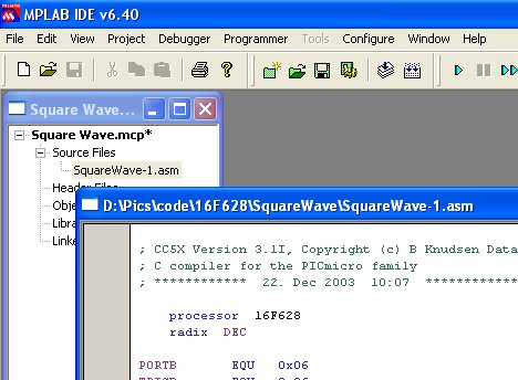
MPLAB is the free software IDE from Microchip. It has many many things built in including something called the stopwatch.
We will be using MPLAB v6.4 so by the time you read this, Microchip will be releasing v8.13 - they really like weekly updates for some reason...
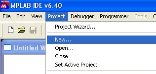
Anyhoots, start a new project with the 16F628. Yes we know the 16F628 has a UART, but this a tutorial right?
From the Configure menu -> Select Device
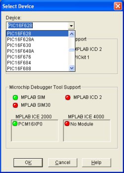
Find the 16F628 and click OK.
Create a new project
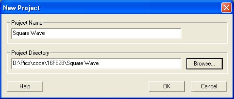
Give it a name.
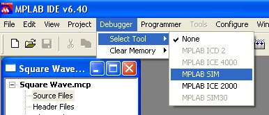
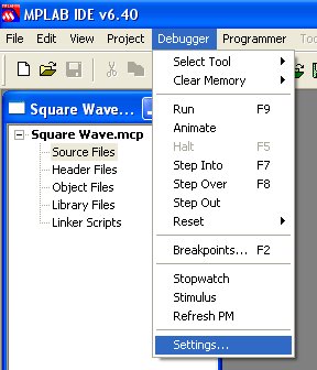
Now you should have a blank MPLAB desktop. Get into debug mode.
We will be using the internal 4MHz oscialltor. Since we are dealing with timing, we of course need to let the software know this!
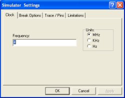
Make sure it is set to the frequency you want to operate at. Some PICs such as the 16F819 have an internal 8MHz oscillator, or you may be running with an external 20MHz crystal. For this tutorial, we chose 4MHz.
Did you see the StopWatch on the Debug menu? We know you want to click it.
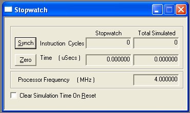
Oooh - Fancy.
So you should have MPLAB setup and ready. Now we need some code to debug and time!
Here we look at turning on and off a port pin at a unknown speed. The StopWatch will be used to infer how fast certain loops will complete.
We need to create a simple C program for testing. This C program will be compiled by CC5X into a ASM file and a HEX file. The HEX file can be loaded onto the PIC directly, but we really don't care about it. MPLAB can handle ASM files, not HEX files.
Get to it!:
Page 1 : The basic RS232 timing layout and requirements
Page 2 : Setting up a project under MPLAB
Page 3 : About StopWatch and Debug functions
Page 4 : Using the StopWatch to tailor delays used in RS232 timing
Page 5 : Hardware connections and HyperTerminal setup
Here is the basic C code of our example program (Squarewave C ASM HEX):
void main()
{uns8 x;
PORTB = 0b.0000.0000;
TRISB = 0b.0000.0000; //0 = Output, 1 = Input
while(1)
{RB0 = 0;
for(x = 0 ; x < 10 ; x++);
RB0 = 1;
for(x = 0 ; x < 10 ; x++);}
}
So RB0 will be pulsed on and off according to the time it takes the for() loop to complete. With this C code compiled, we've already stated we get ASM and HEX files, let's look at the Assembly file.
; void main()
; {
main
; uns8 x;
;
; PORTB = 0b.0000.0000;
BCF 0x03,RP0
BCF 0x03,RP1
CLRF PORTB
; TRISB = 0b.0000.0000; //0 = Output, 1 = Input
BSF 0x03,RP0
CLRF TRISB
;
; while(1)
; {
; RB0 = 0;
BCF 0x03,RP0
m001 BCF 0x06,RB0
; for(x = 0 ; x < 10 ; x++);
CLRF x
m002 MOVLW .10
SUBWF x,W
BTFSC 0x03,Carry
GOTO m003
INCF x,1
GOTO m002
;
; RB0 = 1;
m003 BSF 0x06,RB0
; for(x = 0 ; x < 10 ; x++);
CLRF x
m004 MOVLW .10
SUBWF x,W
BTFSC 0x03,Carry
GOTO m001
INCF x,1
GOTO m004
; }
Jeesh that's ugly. Another great thing about CC5X is the inline C code comments, so you can actually tell what the various assembly statements are doing. For our purposes, we want to focus on the instructions pertaining to the for() loop. There are quite a few instructions there, and I really don't feel like following it by hand. So let's us the StopWatch!!
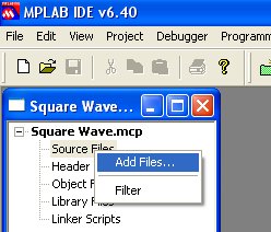
Back in MPLAB, add the SquareWave-1.asm to the project.
Once the ASM file is added to the project, double click on it to open it up on the MPLAB desktop:
With the new file added, we will need to re-build or re-compile the project.
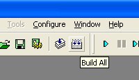
Hit the Build All button and MPLAB should sucessfully build your project. We can now start debugging!
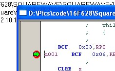
We want to find out how often the RB0 pin will be turning on and off so we will need two break points. The first breakpoint will be when RB0 goes low, the other will be when RB0 goes high.
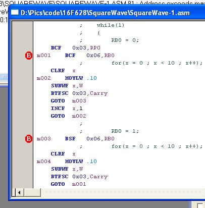
Double click on the grey bar beside these lines. The red 'B' will appear. BCF and BSF is clear flag and set flag. These Assembly commands are clearing and setting the bits associated with the output drivers on Port B. I really don't want to go into the various assembly commands (we actually don't know them!), but you should be able to associate the C commands with the in-line assembly commands.
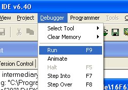
Now run!
The debugger should quickly run to the first breakpoint.
Got it.
Now find the StopWatch window, it will most likely have some values in it. We don't care how long it took to run from power on to the first breakpoint, so hit the Zero button to reset the stopwatch.
Now run the debugger again.
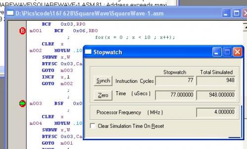
Here's the good stuff. The stopwatch tells us that it took 77 cycles to get from Point A to Point B - 77us at 4MHz.
Now if you Zero out the stopwatch and run the debugger again, it will run from Point B to Point A. Stopwatch = 77cycles = 77us. Therefore! We should have a square wave with a perfect 50% duty cycle at:
1/ (2 * 77us) = 6493.51Hz
So what? Well now that you are familiar with using the StopWatch and using loops for time delays, we can now push the envelope and get perfect 57600bps timing.
You should now be comfortable with the debugger and stopwatch. Now let's take a look at a more complicated case - 57600bps serial timing.
1 second / 57600 bits = 17.361us per bit
So our soft_rs232_out() routine needs EXACTLY 17.36us between bits. Well with a 4MHz oscillator we can only resolve 1us - either 17 or 18us. Luckily, we can get away with some error. Since the host machine (the computer using some terminal program) samples the incoming bits near the middle of the pulse, we can actually get away with highway robbery.
Get to it!:
Page 1 : The basic RS232 timing layout and requirements
Page 2 : Setting up a project under MPLAB
Page 3 : About StopWatch and Debug functions
Page 4 : Using the StopWatch to tailor delays used in RS232 timing
Page 5 : Hardware connections and HyperTerminal setup
Here is the basic C code (serial-out C ASM HEX):
void main()
{PORTB = 0b.0000.0000;
TRISB = 0b.0000.0000; //0 = Output, 1 = Input
while(1) soft_rs232_out('r');}//End Main
Simple, no? What we really care about is the soft_rs232_out() routine.
Here is the first un-timed version of serial-out.c:
//Sends out RS232 levels - nate out at 4MHz 57600 Baud
void soft_rs232_out(uns8 nate)
{uns8 l, i;
//Hold the start bit for ~17.36us
Serial_Out_BB = 1;
nop(); nop(); //nop();
for(i = 0 ; i < 3 ; i++);
for(l = 0 ; l < 8 ; l++)
{//We need ~17.36us between each write to //Serial_Out_BB
Serial_Out_BB = !nate.0;
nate = rr(nate);
nop(); nop(); nop(); //nop();//nop();
for(i = 0 ; i < 2 ; i++);}
//Hold Stop bit for ~17.36us or longer
Serial_Out_BB = 0;
for(i = 0 ; i < 3 ; i++);}
Now all of these various delay values are VERY tentative. We actually pulled all these from a routine designed for 8MHz not 4MHz. Compile the code (or download the ASM file), and get the ASM opened under MPLAB.
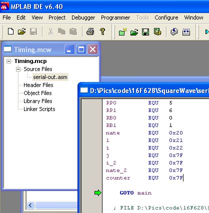
As you can see, we have a new project with the serial-out.asm file attached and open.
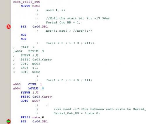
First, let's set the timing between the Start Bit and the First Data Bit. It should be 17us.
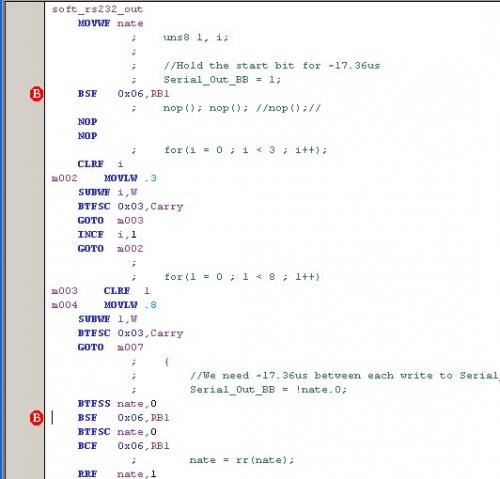
Here is an important picture. We REALLY want to know the time between RB1 changes, nothing else. So be sure to set your breakpoints on the instructions that change the pin, not some other erroneous instruction. Now run the stopwatch.
Hmm - 36us. Way long. How to fix it? Start getting rid of stuff. There is currently a for() loop set to 3 loops and 2 NOP commands. Let's axe the for() loop.
Here we've commented out the for() loop instructions. Now we must re-build the project.
Whoa! 9us. See what we mean by tweaking? Using a combination of the for loop and some NOPs, get the timing to 17us.
Removed For Loop, 2 NOPs = 9 us - Too Short
For loop set to 1, no NOPs = 20us - Too long
For loop set to 0, no NOPs = 13us - Closer
For loop set to 0, 4 NOPs = 17us - Whew!
Yes, using a for loop like:
for(x = 0 ; x < 0 ; x++);
may seem a bit silly, but is serves as short and dirty delay. The for loop is essential for longer delays where the number of NOPs is greater than the code needed for a for() loop. In other words, the code size on the for() loop is constant but the delay changes. The code on a NOP is kind of variable (depending on how many you need), but the delay is constant for each NOP command.
Note: The if you try to set the above mentioned for loop to x<0, the CC5X optimization engine will tear it out and just stick in a x = 0;. Watch your ASM file closely.
Another trick is to tell the PIC to 'skip' to the next instruction. The PIC has to load the address of the instruction to goto (even though it's the very next instruction). This takes an extra cycle, but uses the same code space as a NOP. CC5X does this with the nop2(); command. Two NOPs for the price of one! This is a little tighter code - so we went with this choice. If code length is not a worry, make the code as EASY as possible for you to understand.
We REALLY don't deal with assembly at all. All of our tweaks are done in the C code and then re-compiled. When you switch back to MPLAB it will ask:
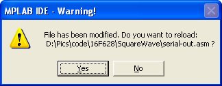
Of course you will want to re-load MPLAB with the newest version of the ASM file.
Nuther Note: If you insert code or re-assemble, the MPLAB breakpoints will get moved to the wrong position. Always make sure your breakpoints are in the correct spot when using the stopwatch.
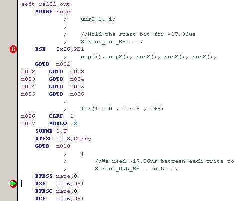
The final Start Bit timing using 5 - nop2() commands. 17us, minimal code space. Fancy!
Now we need to set the timing to 17us between Data Bits.
More trickiness. We must set RB1 according to the bit in our outgoing byte. But if it's a '1' we must clear the flag, and if it is a '0' we must set the flag. Because we must make a decision, the code length is not constant.
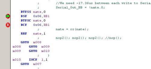
Here you can see we used three nop2(); trick statements to get the timing close to 18us.
The time between bits varies depending on the previous bit. Sometimes it's 16, 18, or 20us. This is what we mean by highway robbery. Even though the PIC is not outputting solid timing, the receiving machine can still understand the signals because the receiver is looking at the middle of the bit, not the rising or falling edges.
Finally, all that is left is the Stop Bit.
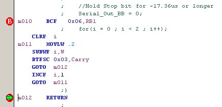
The Stop Bit set to 21us using a for() loop set to 2.
Here is a good example of where the for loop is better than NOPs. We need something at least as long as 17us. It would take more instructions using NOPs to get that timing. Instead, we opted for a for() loop set to 2. This will take 21us which is a little long, but the stop bit can be as long as you want. This is the most compact code that we could come up with that still fulfills the 17us minimum delay.
Now does it work?? We took our C code that has the corrected C commands to fit the timing requirements and compiled it a final time. You can now double check the timing under MPLAB. We loaded the generated HEX file onto a 16F628 and tried it out...
Normally you would use a MAX232 IC to convert TTL 5V signals to RS232 +/-12V signals. We will show a quick and dirty means of connecting the PIC directly to the computer without the means of a RS232 converter.
Get to it!:
Page 1 : The basic RS232 timing layout and requirements
Page 2 : Setting up a project under MPLAB
Page 3 : About StopWatch and Debug functions
Page 4 : Using the StopWatch to tailor delays used in RS232 timing
Page 5 : Hardware connections and HyperTerminal setup
Connect PIC pin RB1 to Pin 2 of a DB9 header. You'll also need to connect the GND of your circuit to the Pin 5 (GND) of the DB9 header. The easiest way we've found to do this is solder some wires onto a DB9 female solder cup. Jam the open leads into a bread board and viola! you have an RS232 connection.
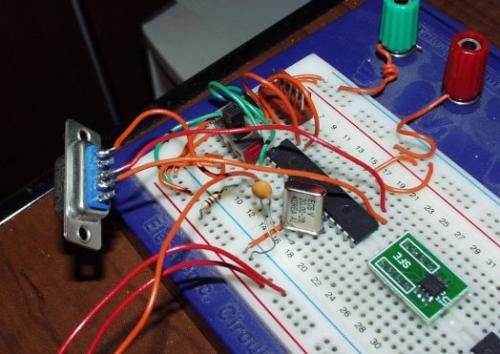
DB9 Female header attached to a PIC 16F873A. Notice the missing cap on the xtal? We didn't use this specific setup... But we could.
If you look closely, most DB9 solder cup connectors have the Pin designations molded on the plastic - very handy for getting your connections correct.
Now open hyperterminal and set it up for 57600bps operation.
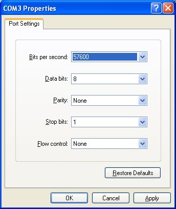
Comm3 set to 57600bps.
If the 'Configure' button is grayed out, make sure you hit the 'Disconnect' or 'Hang-Up' button before you try to configure the comm port.
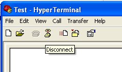
Of course, remember to re-open the Comm port after you have it configured! Hit the 'Connect' or 'Call' button.
Now turn on the PIC! Don't worry, it didn't work for us either. Just a bunch of garbage.
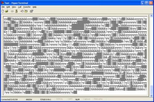
What's the deal? My thoughts are that the timing is so fuzzy that we have to put a lot time between bytes so that HyperTerminal can link up correctly. If we display one letter at a time with a big delay in between characters, there is no problem. But if we try to display the same letter immediately back-to-back, HyperTerminal gets lost. We discovered that increasing the stop bit to ~56us allows for a good transmission.
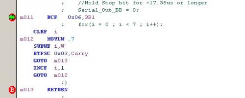
The final stop bit using a for() loop set to 7.
And we still get great transmission rates!
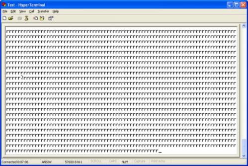
A beautiful site - minus the little blip.
Okay, now what?
Well, we've discovered that 9600bps is useful 90% of the time. Only on certain projects will a higher data rate be necessary. As you can see, higher rates become more and more difficult. Using these debugging and tweaking techniques, you should be able to implement a software UART of pretty much any rate. We have very successfully implemented 115200bps on the 16F819 because it has a higher 8MHz internal oscillator. With a 20MHz external crystal the timing becomes even easier!
The great thing is that once you have the timing down, you don't have to worry about it ever again. Over time we've created different soft_rs232_out() routines for different permutations of data rates and crystal speeds. By setting the definitions at the top of the program file, the correct one gets compiled. Really handy once everything gets setup correctly.
cool