
Basic breadboard tutorial
So you want to start burning your own PICs? We've written a short tutorial to help get you started.
We assume you are starting from scratch. We tried to write it for the beginner with little knowledge of bread boarding - skim as you see fit.
What you need:
-
PIC Programmer - We will use the PIC-PG1 low-cost serial programmer
-
Programmable PIC of some flavor - 16F628, 16F873, 16F877
-
Voltage Regulator - LM317 variable or 78L05
-
Power Supply - 8V 'Wall wart' or above
-
Multimeter - You just can't leave home without it!
-
Hook-up wire - 22 American Wire Guage (AWG) wire works well
-
Bread board - Used for quick prototyping
-
Needle Nose Pliers - It can be tough jamming things into the bread board
Alrighty - so you've got most of what's on the list and you are ready to get going.
First you have to set up the power circuit.
Power Circuit -
Most of the circuits you will deal with operate on a 5 volt DC supply. Your house is 120 volts AC. How to make it work? Get a 'Wall Wart'. These are the large black boxes you plug into the wall to power your cell phone charger or cable modem. Checkout the label some time. It should say something like:
-
Input: AC 120V 60Hz
-
Output: 12V 500mA
If you plug this transformer (wall wart in engineering speak) into the wall, the cylindrical plug will output 12V and be able to source 500mili-Amps. If you are shopping for one, try to find one between 8-20V and 300mA to 1A DC. The Amp rating is not important for your first project. Blinking a light and running the PIC will only require ~20mA. A minuscule part of your transformer's ability.
But if most of the circuits run at 5V what are we doing with 12V supply? The wall warts produce a very 'noisy' 12V. We will clean that up with a 78L05 voltage regulator. If you apply some noisy voltage to the VIN pin, you will see a relatively clean 5V on the VOUT pin.
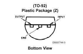
What you want to do is attach the positive line from your wall wart to the input pin of the VReg. Attach the ground line of your wall wart to the ground line of your bread board. Then plug a wire from the 'Output' pin to the power strip of the bread board along with a wire connecting the 'GND' pin to the Ground strip of the bread board.
All Voltage Regulators require 2-3V of 'over-head' voltage. This means that you must throw a few more volts on the input than what you are using on the output. This is because the internal circuitry has losses. If you try to pass 5-6V through a 5V regulator, nothing will break, but you will only see an iffy 4V on the output side. Try to give the 5V regulator at minimum 7.5V.
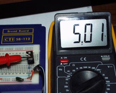
Whip out your trusty multimeter, plug in the wall wart, and measure the voltage between the high and low power strips on the bread board. You should read a voltage around 5V.
It is a good idea to hook a .1uF Capacitor between the high and low lines. This capacitor helps reduce any AC transients in the system. Tran what? The cap acts as a surge suppressor. When your roommate kicks on the blender and the lights go dim, the wall wart is going to pass a mild power spike to your circuit. The voltage regulator will suppress most of this spike, the capacitor helps suppress it even more.
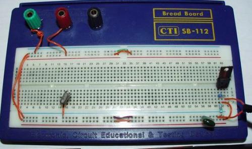
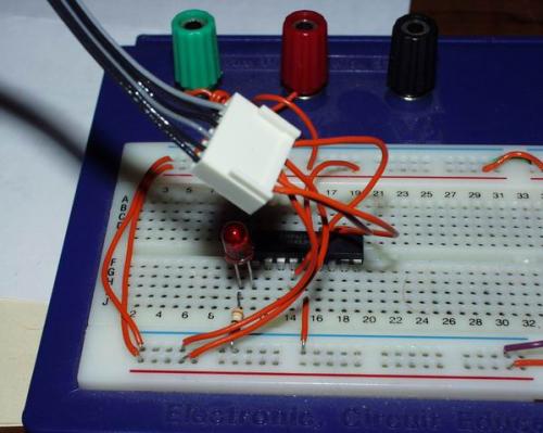
The power circuit with the power strips conjoined
All ways test your power circuit before putting a microprocessor near your board. If something is hooked up wrong, or backwards, ICs can instantly fry. You will not see any smoke, but you will be scratching your head for hours trying to figure out why the darned thing doesn't work.
Warning - If you smell something odd or sense heat coming off the voltage regulator, immediately unplug your circuit. If you have a short of some kind, the VReg will begin to pass all sorts of current. This current turns to heat and causes the VReg to heat up dramatically. I have burnt my finger a number of times 'testing' the VReg. Under normal operating conditions, the VReg should barely be noticeably warm to the touch. If this is not the case, unplug and check.
So we will assume you've got your power circuit setup and ready to go.
On to the next step - Microcontroller Implantation.
Additional Discussion -
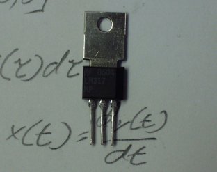
The LM317 on some Linear Systems Homework
Let's say you can't get your hands on a 78L05, or you want another voltage for some other module of the project. You need a LM317!
The LM317 is an adjustable regulator that can output 1.25V to 37Volts! It does this with two resistors and a feed back loop. You simple pick two resistors based on the datasheet equation:

Where R1 is 240-Ohm. You may ignore the IAJD term for the most part.
And hook them to the 'ADJ' pin as follows:
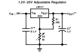
The capacitors C1 and C2 help and are good engineering practice. But if you don't got them, don't fret. They are only AC surge suppressors.
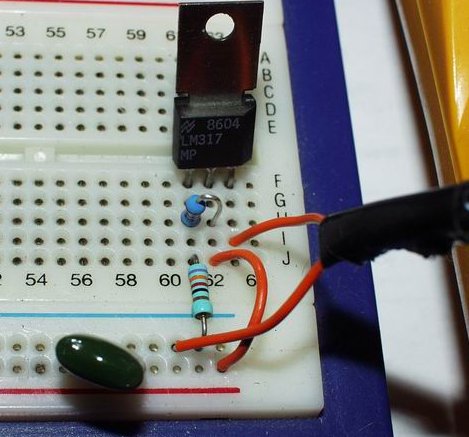
Our LM317 configured for 5V operation
With R1 as 240-Ohm, R2 as 720-Ohm, VOUT you get 5V out.
The following link is a fun graphical calculator for resistors. Have you got a pile of resistors and no idea what they are? Look 'em up!
http://samengstrom.com/elec/resistor/index.html
She's got power captain! So now what? Time to get the uC hooked in.
Put in the PIC -
Again, double check that you've got 5V across your power strips. Red is Vdd (5V), Blue is Ground. Unplug your circuit and insert your PIC.
We will be using the 16F628.
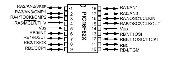
Connect the Vss pin to ground, the Vdd pin goes to 5V. The great thing about the '628 is that we do not need to pull-up the MCLR line, or use an external Xtal. You are welcome to use any frequency you wish. Read the data sheet. The '628 is capable of running with on onboard 4MHz Xtal (no external Xtal needed!), a External Resistor mode, and a few other oscillating modes.
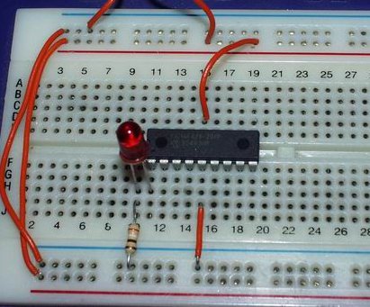
Pin 1 of and IC always has a dot or some other asymmetrical marking
Connect any old LED from RA2 (the left most, bottom row pin). Checkout PIC-LED Tutorial for specifics of hooking up the LED. You need to know the curved side (anode) connects to the pin and flat side (cathode) to the current limiting resistor (we used 390-Ohm), and the resistor to ground. This way, when RA2 goes high, the LED will see 5V, light up, and the resistor will limit the current so the LED doesn't blow.
For our first project we are going to make an LED blink. Sounds easy? Just wait - it took us many days of scratching our head and about three fried PICs before we learned what not to do.
You should have the basic wiring in, now we need to get the thing programmed.
On to Programming!
Chip is in. Time for the In-Circuit-Serial-Programming
The code you will need:
- blink.hex - the PIC loadable file for blinking
- blink.asm - the assembly file
- blink.c - the file that we created in C
ICSP -
In-Circuit-Serial-Programming is the greatest thing since sliced bread and SPAM-burgers. You will find very quickly that pulling a chip out of a bread board and jamming it in a socket, programming, and then back into the bread board can be cumbersome. You will bend a pin eventually.
ICSP will allow you to burn and test much faster than you could have before. But it does take some setting up.
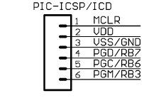
The Olimex ICSP header
To program a PIC with ICSP, 5 lines are needed. First, you must power the PIC - Vdd and Vss, 5V and Ground. Next are the data lines. The program is transfered serially through RB7 and RB6. Finally, the MCLR pin must be pulled up to 13V so that the PIC realizes it is in programming mode. The last pin on the ICSP header is for debugging and will not be used in this tutorial.
Make sure the programmer is not attached to the computer. See warning below for more info.
Take five wires and jam them into the Vdd, Gnd, MCLR, RB7, and RB6. Connect these wires so that the MCLR line is as follows:
Pin 1 of header connected to the MCLR line
If you look very closely this pin on the header reads "Cl31 AF". Be very sure you connect the Vdd and Gnd correctly. We got a little cocky and quickly connected the wires incorrectly while we had the circuit powered externally. After a funny smell and (literally) a small rising cloud of smoke we decided to unplug the circuit and take a look. We were lucky we didn't melt the computer. And oddly enough, the super toasty hot voltage regulator still works, so does the programmer! Way to build 'em Olimex!
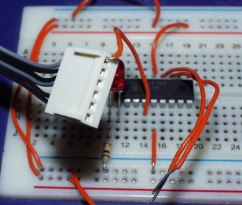
Everything connected correctly
Open up the handy IC-Prog. And load the blink.hex file.
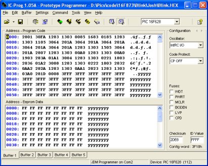
IC-Prog configured for programming
Once you have your HEX file loaded, make sure the configuration settings are correct.
-
Select 'PIC 16F628' in the drop down box.
-
The 'Fuses' on the side of the screen control the low-level functions of the PIC. These are normally set at the beginning of your code. Make sure you turn these off until you read the datasheet and implement them correctly within your code.
-
Turn code protect off - you shouldn't need to protect your blinking light from any PIC hackers.
-
Double check that the Oscillator is set to Internal RC.
-
If you are operating under XP/NT you will need to turn on the NT/2000/XP driver. This has something to due with how the XP/NT Windows kernel deals with serial I/O. This driver file can be found on the IC-Prog website.
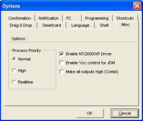
Special NT/XP driver option
Once you have everything set, go ahead and try to 'Program All'. If you can successfully program your PIC, you've done very well!
If not:
-
Check the connections. Make sure you have the header oriented correctly as shown.
-
Make sure you have the correct Com port selected.
-
Close and re-open IC-Prog. This will re-initialize the serial port.
You can always chose the 'Read All' option to read what is on the PIC. This is a nice quick test to make sure everything really did transfer over.
You should now have a PIC with some sort of code loaded onto it.
Warning - The computer provides power through the serial port. If you have programmed your PIC correctly, do not be surprised if your LED is blinking. The serial port is passing power through your dongle programmer into your bread board. Be careful with the Gnd and Vdd wires. If you short these you may send a short through your serial port to your mother board. Always unplug the dongle programmer from the serial cable before hooking up or re-arranging wires.
Ready? Time to plug in the beast.
The PIC is wired and programmed. Cross your fingers and flip the switch.
It shouldn't be that dramatic. Plug in the wall wart and use your multimeter to make sure you've got 5V supply. The LED should be blinking. Use your multimeter to monitor RA2 - the pin the LED is attached to. You should see the voltage flip back and forth.
Odds are it didn't work. A few things to check
- Make sure your Vdd and Vss pins are connected correctly. Check with the multimeter.
- If the LED is not lighting up, plug it in the other way. LEDs have polarity and you might have the anode and cathode switched.
I have been searching for an answer and I can't find it I am hoping someone here can answer or direct me somewhere that can answer. Here is my question when do you use a 4,5 or 6 band resistor? For example, the project I am working on right calls for a 100k ohm resistor now which should I use a 4,5 or 6 band resistor?
4 band resistors have the 4th band as tolerance and only have the values of gold or silver (5% or 10%). If you start getting tolerances of less than that you will need more than 2 digits (plus a multiplier) to get specific numbers. 5 band resistors give you 3 digits (plus a multiplier). 6 band resistors also offer a temperature coefficient band. So if you don't care about temperature coefficients you can use a 4 or 5 band resistor and if you don't need super tight tolerances a 4 band resistor will work fine. A lot of the time you are using resistors to current limit LEDs or provide pullups or pull downs where the exact value isn't really that important anyway which is probably why 4 band resistors are pretty popular. I'd say if there is no mention of what tolerance is needed a 4 band resistor should be fine.
One more question: Can I use DC voltage for this tutorial, such as, a 9V battery?
Yes you can, but in the long run, its better to buy dc supply.. :)
Hi,
I am a newbie with electronics. I have a couple questions when going through this tutorial.
a. Just found out that my breadboard can't seem to fit the pin size of the LM317 voltage regulator in orientation like your image shown. So, I had to spread the pins out a bit to fit them diagonally, so that each pin would occupy one hole on each different row. That's such bummer, as I don't know if it's a feature of my breadboard or not. So, what kind of breadboard you use in this tutorial? It seems like size of holes are much bigger than the ones on my breadboard.
b. How would I find the exact the resistors used with the exact ohm values to be used with the LM317 above so that I would have 5V output, that is, the 240 ohm and 720 ohm resistors? Is there a resistor calculator that would give me the color bands if I input the ohm and the tolerance? (LOL: I've got 1000 carbon film resistors and none of which has the exact ohm requirements for this tutorial. :-(
Thanks
LOL...I could put series of resistors to make up the 240 and 270 ohm values.