
Reflow Skillet
I've been reflowing SMD parts on PCBs for around a year now. Spark Fun has barely had the capitol to invest in a hot-air rework station, let alone pick and place machines and industrial reflow ovens. Luckily, as business has increased, revenue has allowed us to purchase a few bottom-dollar machines to help with manufacturing. I'm here to tell you, it was all a waste of money...
Don't get me wrong, there is the correct way to manufacture 10,000 units of a caller-ID controller board, and then there is the Spark Fun way. If you're reading this, you're like us - strapped for cash and in need of a good way to reflow PCBs.
Here is a tutorial that will break down the different approaches to SMD reflow soldering, what we've learned, and what to steer clear of.
As always, this stuff can kill you, burn your house down, or make your basement smell pretty foul. Don't try any of this at home - wait, you are at home. Well, just take everything we say with a grain of salt.
SMD Reflow Tutorials:
There are five ways to solder SMD parts that I can think of:
- Hand Soldering (default)
- Toasting (ok)
- Industrial Reflow (pretty crummy)
- Hot-air Rework (very nice!)
- Hot Plate Reflowing (winner!)
Hand soldering is cheap (no extra equipment needed). You will need a decent iron, but nothing else. $100 is pretty standard for an iron although $50-$2000 is possible.
New users to soldering SMD devices are always intimidated by soldering itty-bitty leads. Believe you me, it can all be hand soldered.
Common questions:
- Do I need a microscope?
Maybe. I've never used one but Pete does. With a little practice, we can see disconnects and color variations that indicate problems with the naked eye.
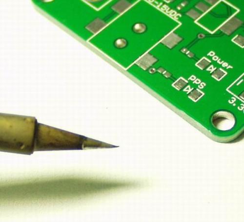
- Do I need a super fine tip?
Probably not. Don't even think about trying it with your $10 Radio Shack fire starter! But a conical tip of small size works fine. A heftier tip can be beneficial in some cases (helps to move solder blobs).
- I certainly can't hand solder XY type package!
No really, you can! No matter how small the pitch, even leadless QFN packages, can all be soldered with some solder wick and some solder ball chasing. It's not easy and not fast, but it can be done. The only exception is BGA which I've never tried with an iron. But get creative! All you have to do is heat up the overall area. Soldering from the back side of the PCB using vias as heat ducts has worked for other people.
Over all, hand soldering is the way to do it when other means are not available.
Pros:
- Soldering equipment most likely to be available
Cons:
- Very slow
- Boards get dirty with all the flux running around
- Heat stressing can lift pads if the soldering student is new to soldering
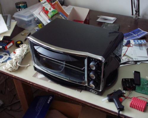
Using a toaster oven has been shown to work in many cases. A $50-$100 toaster oven from your local Wally World can do quite nicely. The Seattle Robotics Society's report on Toaster Oven Reflowing covers the process nicely. I've even built up a controller board to try to mimic the real reflow oven profiles.
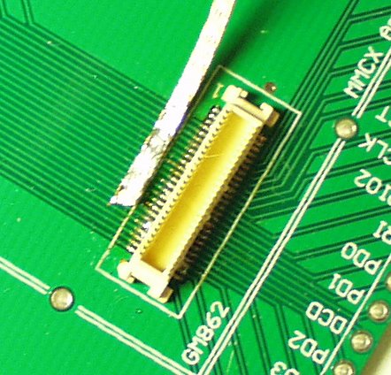
Ben and I have found that many plastic connectors have low melting points while other connectors (SMD USB connectors with metal housings) have very high reflow points. This was a major problem on the GM862 EVK v2 boards. Time and time again, either the USB connector would fail to reflow because of the metal housing reflecting the heat, or we would bake the board so long that the USB would reflow but the plastic Camera connector would be completely hosed. In other words, you have to destroy the plastic connectors or have larger connectors pop off in your hand. The main culprit in our case was the over-head heating elements in our industrial reflow oven. Since our toaster oven has elements on both top and bottom (the top elements heats up much faster), a toaster oven would have the same Achilles heal, melting the softer components on the top side of the PCB.
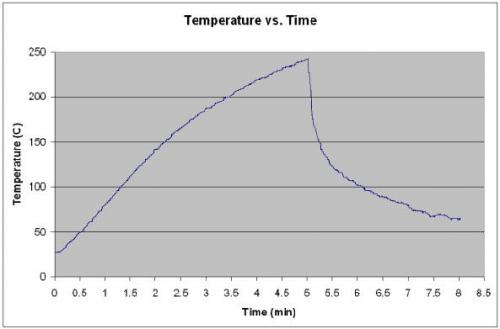
Here we have the initial test of the Spark Fun Oster Toaster. Starting from 25C, the ramp is 225C in 5min or 45C/min = 0.75C/s. This is actually pretty good. The commercial reflow ovens are 1-1.5C/s. The massive drop at 5min is when the front door was opened. The toaster can actually hit 250C without any problems.
In the end, toaster ovens work, but they are too dependant on external control or attempting to view inside the little window waiting for something to happen. Over-head elements run the risk of melting plastic connectors to the point of destruction.
Pros:
- Pretty cheap
- Works well
Cons:
- Difficult to know/see when to open the door when the boards have fully reflowed
- Can melt plastic connectors
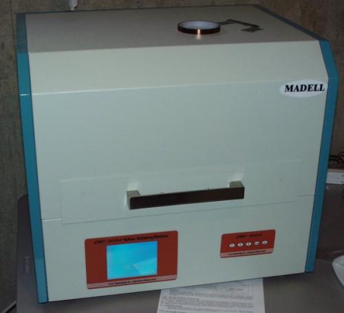
Don't get me started. We dropped $2300 on a reflow oven from Madell Tech because we didn't know any better. It was a good lesson learned. The oven is fairly large so shipping was pretty steep. The unit runs on 220V and came with some incompatible Chinese plug on the end.
Some pictures:
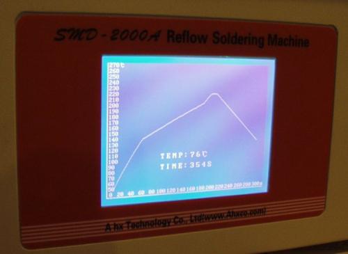
The profile can be set to any temperature over any length of time through this fancy LCD and a couple tactile buttons.
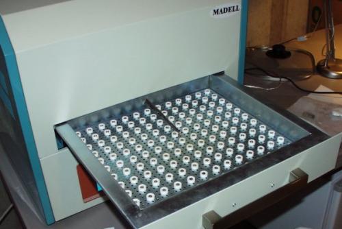
As you can see, the tray is pretty large. The oven has fans built in for cooling. The elements are IR which heat very quickly allowing the temperature to be monitored very closely. The slim brown thing is the temperature sensor that is supposed to be taped to every PCB that is reflowed - something we've never done.
As stated above, this thing is a problem because there are cold spots where the USB connectors never reflow. If we tweak the profile up high enough to reflow the USB connectors, the plastic connectors melt. We've had repeatability problems, etc, etc. We continue to use the oven for large batches. It could easily be an operator error - we may be missing something simple. Either way, we are happier with our $30 hot plate.
Pros:
- Interface is beautiful
- Larger capacity
- Absolute profile control
Cons:
- Runs on 220V
- Expensive
- Very large footprint
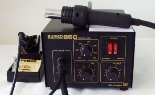
This is a favorite around the office. Using these cheap rework stations saves time and money.
Common questions:
-
Which nozzle do I need?
Actually, we stuck the basic small circular nozzle on there and have never taken it off. The hot air just sort of flows everywhere heating of the immediate area of the PCB.
-
Which type of unit do I need?
I noticed the other day, the digital stations will tell you precisely what temperature is leaving the nozzle, but what is the temperature of the PCB? Who cares? Most applications dictate that the temperature be lower than some threshold, but the overall temp does not matter. All that matters is that it is hot enough to melt all solder joints at the same time. Given enough time, you can truly warp a PCB, boil off the solder mask, etc. It's a tool that takes practice and learning. Nothing too major - we love em!
Pros:
-
Decent price for great versatility
-
Can save almost any IC/part
-
Can fix almost any messed up solder job/placement problem
Cons:
-
Could burn your house down - no auto shut-off
-
Using a hot-air gun for reflowing can take a long time (5 minutes a board)
Finally we get to the point of this tutorial... After playing with all of the above, we were still being forced to hot-air fix some boards, solder on others, and had even more problems with others.
The reflow oven was melting some boards and not reflowing others. Hot-air was taking far too long, hand soldering was out of the question. The toaster oven was cheap, but would have similar problems to the IR oven. Finally, Ben and I wondered why we couldn't use a hot plate to heat just the PCB - this would protect the plastic parts and should reflow the USB connectors better (heat transfer is better because the IR heat was bouncing off the metal housings whereas the hot plate heats the PCB directly). $32.44 and another short trip to Target and we've got ourselves a hot plate!
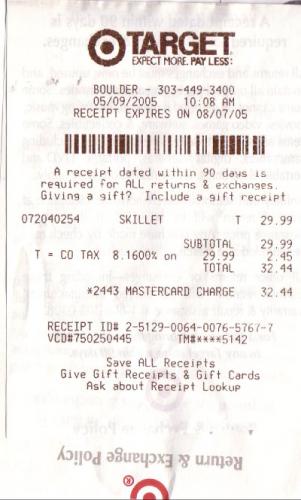
Holy smokes - I could take this thing back in 3 months!
Okay, so it's actually a hot skillet. There was a hot-plate for $19.99 but I decided it was a bit small and opted for the larger skillet with lid (might help, right?).
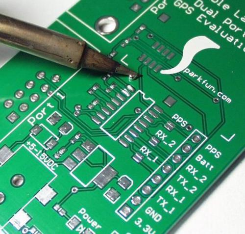
So I have Ben whip up a Lassen iQ breakout board with the evil USB connector and tricky USB CP2102 IC. We grab a temp gun to watch the temperature of the skillet. The dial controller reads up to 450F(230C). This should be more than enough...
So we plug 'er in and let 'er go. It was probably 2-3 minutes of staring before the temperature hit ~200C and we noticed the smaller components reflow. As expected, the USB connector took an additional 20-30 seconds of ramping up heat. Finally, after the USB solder connections looked good, shiny, and liquid, we turned the dial to off and waited for the board to cool. A quick test and the board passed on the first try! The USB connector was soldered solidly to the board and all plastic parts survived. The only noticeable problem was the silkscreen on the plate side (PCB bottom) was slightly lightened as if some of the ink had been removed - though it was still white...
How about some pictures? This is the CP2102 breakout board, in a panel of 4x3.
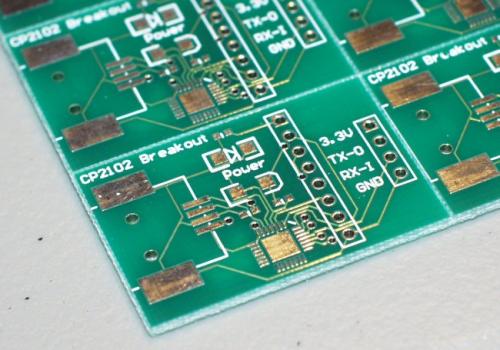
V-scored PCB before paste application. We use Kester Easy 256 solder paste. For more information about how to stencil solder paste - have a look at our solder paste tutorial!
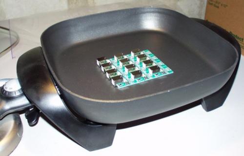
The hot skillet reflow-er
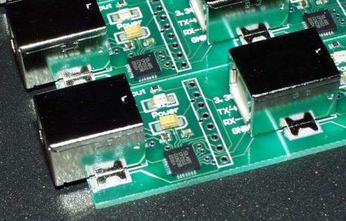
Baking - at about 100C. Notice how all the paste looks grey and dusty.
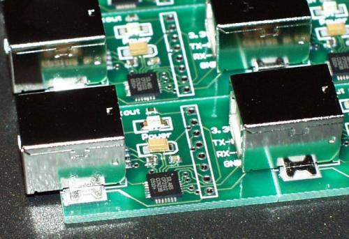
The Power LED and one side of the tantalum cap have reflowed ~200C

All small components are flowed - ~210C
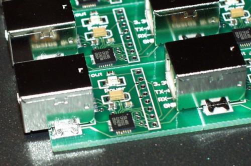
USB now reflowed ~225C
The pictures don't show it, but it is actually very easy to tell when the solder paste has turned liquid.
This panel was much trickier to reflow as the skillet has a circular heating element. The center is the coolest part. By sliding the PCB around (wonderful Teflon) I was able to position the various problems spots to a hot spot in the skillet. The smaller, circular, $20 unit from target may have a better element.
I don't think anything can replace the large scale, multi-zone, IR/convection reflow ovens. But I could by 100 hot plates at $30 a piece before coming close to the price and performance of a traditional reflow oven.
Pros:
-
Low cost
-
Works well
-
Available anywhere
-
Small footprint
-
Operates on 110V
Cons:
-
Non-uniform heating area
-
Skillet sides can burn arms
Email us! spark at sparkfun.com
One very old trick for getting an even heat distribution is to put a layer of clean dry sand at the bottom. I think about 1 cm (0.5") would be fine. The sand will spread the heat and you will get a "softer" and more evenly spread heat.
Since the sand will also retain or store heat you will not be able to accomplish any high speed changes in temperature, but I do not think that will be a problem. The sand is dry so there should not be anything to clean from the soldered boards unless some paste has found its way to the bottom side.
Regarding the use of Electric Induction Hot Plates:
FYI, just a disclaimer that I am a physics student researcher accustomed to dealing with what can be VERY picky/delicate electronics and obscenely powerful superconducting magnets. So in general we worry all the time about things that most electrical engineers would be able to safely ignore.
As I understand it any kind of induction stove is a transformer whose primary coil is the "stove eye" and whose secondary coil is whatever pot or pan you are using.
I would be concerned about the effects of a powerful changing magnetic field across a circuit board that probably has all kinds of stuff that would be delicate to small currents at relatively small voltages. I can see how people would wonder how much of an advantage would be gained by heating the copper layer in a PCB board this way, for instance... but just remember that all you are doing is flowing a current directly through the electronics as a method of heating it up. You would need enough ferrous metal to respond in this way to the changing current but that just means it could end up melting iron cores of inductors on the board before affecting anything else. Then there is using the induction to heat something that then in turn heats the PCB, one argument can be made that the amount of control (similar to gas stoves) over the heat could allow for more precision. But the question can be asked is this: is it worth more temperature control to deal with a somewhat powerful, low-frequency oscillating magnetic dipole. Remember that these are fields that are designed to induce enough current in an iron pot to boil the water inside. In fact the manufacturers of induction stoves specifically say not to use tin foil because the induced current will cause it to melt.
Very fun question to think about in any case!
"As I understand it any kind of induction stove is a transformer..." Any hotplate not described explicitly as (expensive) "induction" will be heated by a resistive heating element, no induction involved. You can heat, e.g., a thin-walled coffee jug; no induction involved. From the price and description of those described here, they do not use induction. (I also have worked with big magnets - if you went near one with a clockwork watch it wouldn't just be magnetised and affected, all the insides would break loose and rattle inside the case.)
Also consider this.. In favor of the hot plate, any magnetic field created by the heating element in the hotplate would be minimized by the opposing eddy current in the plate tube and/or the heating element housing.. It would be interesting to see how strong of a magnetic force is created by the plate. However, while working with flooded plane PCB's I don't think induction is going to be a much of a concern. Especially when you take into fact that it would be 1 trace against how strong of an inductive force? It would be near impossible to convince me that secondary voltage in the board traces is high enough to cause a problem in this scenario.. Thanks for the write up!! Good info!! Perhaps, consider a coated piece of aluminum in the pan to spread heat? Also, allowing more TIME for the board to heat so the differential between board and oven/pan temp is minimized may help you with your silkscreen/board damage problem...? Or do I have that backwards?
The toaster oven.. Here's something that MAY work for you..
There's 3 different kinds of heat.. Convection (Heat passing through a gas or liquid to indirectly heat something), Conduction (Heat passing through a solid much like a transistor to a heatsink) and radiation (Like IR - Infrared, or reflective heat. this is an invisible wavelength produced by things as they burn or heat up.. )
Toaster ovens are RADIANT heaters. they produce Infrared wave lengths that heat objects in the oven but not the oven itself. larger objects absorb (or reflect) the infra red at the same rate that smaller objects do. however smaller objects heat up faster because they have less mass. This is why the smaller plastic pieces fail..
Hot plate/skillet are CONDUCTION heaters. I think the reason you have so much success with this method is because everything heats up at almost the same rate (Give or take the eye of the heating element being the hottest part)
last is CONVECTION.. I think that if you wanted to revisit this Toaster oven idea you may have much better success with 1 minor tweak.. convection heating is preferred since it evenly (Or more even than most methods) heats everything evenly, and is fairly fast. I realize that the element is on top AND bottom on your oven.. If you ever decide to revisit this project, try attaching a heat shield above the PCB, but below the element, and another above the bottom element and below the PCB.. Allow room for air to circulate around these plates. The idea is to heat the air in the oven and reflect the infrared coming from the heating elements away from the PCB so that they don't heat the board. We only want the hot air via CONVECTION to heat the boards as this will prove to be a very even heating of the board by theory. (Consider it to be a huge hot air gun across the entire PCB.)
Let me know if you try this.. Gadgedizzle (at) gmail (dot) com
The solder paste tutorial link is borked!
This approach works great. Because I wanted a bit more heat (I use lead-free solder), I used a hot plate. But I found that I needed much better control of the temperature than the hot plate had. For a detailed explanation, including how to build the controller, check out this Instructable.
http://www.instructables.com/id/Extreme_Surface_Mount_Soldering/
You might try getting a square of aluminum the size of your pc board or slightly larger and set it and the populated pc board in the skillet. That should keep the temp even on the pc board.
Is the skillet in this article an: Oster DuraCeramic 12" Square Electric Skillet in Black/Silver, CKSTSKFM12-ECO Link: http://www.target.com/p/oster-duraceramic-12-x-12-skillet/-/A-14674773 It looks like it might be. I ask because finding a skillet that goes to 450F(230C) is hard to find. Mostly because the product details don't often list the maximum temperature.
The type of heating element and manufacturer have probably changed over the past 10 years but yes, that looks very similar to the one we used. If you get a chance to test it, please post back and let us know how it goes!
have you tried putting a (for instance 1/4" thick piece of flat aluminum stock in the skillet to spread out the heat. Then put board on that. Just an idea I have not tried it but it makes sense from a thermodynamic point of view.
Well the hotplate definitely isn't totally useless especially when you are having one of those weeks where everything seems to be going wrong and your stuck coming into the shop @ 4 or 5am or have to pull another late night, you and Ben can always use it for morning eggs or a late night dinner of grilled cheese or burgers between another sniff of the fumes of the soldering paste you guys must be inhaling. ....
An off the wall thought about methods of gaining appropriate heat for reflowing. A few years back, I purchased a small NSF rated convection oven. It is one of those stainless steel models, that can handle a 1/4 size cooking sheet. My original intention was to use it to make small pizzas. In the process, I learned about cooking stones. I was unable to find any in my needed size, but the local building supply store had a selection of odd/ends of floor tiles. From these I found a few unglazed ceramic tiles. The unglazed tiles worked perfectly in the convection oven, and helped to moderate the heat (because the tiles operate as a heat reservoir). Prior to putting the tiles in, I could barely get the oven up to the calibrated maximum of 450F. With the tiles, I could hit 500F with no problem. This little oven cost me $400 from a restaurant supply store. Might be an intermediate solution (better than the skillet, but less than the big reflow oven). The oven is made by Wisco Industries.
I wonder if somebody has experience to use skillet method above to solder BGA-324 chips? If so, any comments? May be somebody has some references on the topic?
Hi
Hot plates seem to work and skillets with a heat spreader like a alloy plate i think a flat piece of glass might work also and if your a bit scared, try Borosilicate glass (Pyrex) like the lens of a halogen work light http://www.mcmaster.com/ will have some. if you don't have a source like the old junk light in you garage many use regular glass up to 120 c and above on their 3D printers heated bed so i thought i would just add a alternative material for use a help if you have some laying around.
I'll just fix this for you.
But I could buy 100 hot plates at $30 a piece before coming close to the price and performance of a traditional reflow oven.
An additional viable source of hot air for rework and soldering is a gas soldering iron with interchangeable tips; many such have a hot air tip which delivers a very narrow stream of hot air. There are professional-grade ones (e.g. Portasol, which I have) and cheaper ones. Also some devices which have hot air but no soldering bits. Additional, useful functionality is heat-shrinking. Useless (for me) is hot knife to cut plastics, blowtorch nozzle. When looking into what to use, I found reports of people using these tools professionally, as well as lots of non-pro use. They are portable, if anyone needs to do this sort of work on-site (doubtful?). I think I've read of the use of gas blowtorches too.
Anyone worried about damaging devices with controlled heat: in a test reported in Wikipedia article Rework (electronics) at the end of the Reflowing and reballing section (as of mid-July 2013!), 20 devices were reballed professionally several times; none failed, although one went through 17 heat cycles (in 2 out of 20, professional reballing failed, but succeeded when repeated).
Thank you so much for the great tutorial. I've done quite a few done with a skillet, and think it's the best method for one-offs. You just know when to stop the heat.
Aki
Going down this road right now with a 1/2" aluminum plate on order. Is this strategy still good for hobbyists or is there any even better method? Thinking of putting the plate on a cheap electric burner but not quite sure which brand to use. Any suggestions?
Found a hot plate at Walgreens for $15 - perfect! An old circular saw blade evens out the heat nicely.
Hi, please, anyone here already use those Electric Induction Hot Plates instead of the normal electric skillet?
I do demos at the local robotics meetings where I show how to solder TQFP and other IC's using a 1/4 inch wide double bevel tip.
First I use a paint stripper to heat both sides of the board and then I tap the board while it's upside down to remove the parts.
Then I use solder wick to remove all the solder from the PCB so that the part sits in place. I then tack it in place.
Once tacked in place I solder all the pads together in big blobs to make sure there is solder under each pin.
There is then two different approaches at this point. you can use solder wick to remove the bridges or you can do what I like to do and mount the PCB vertically point the tip upward and flow the solder down the tip as you add more solder.
The flow method requires that you tin the double bevel tip back towards the iron so that the solder will flow down the tip, but the big advantage is that it leaves a more consistent fillet.
PS: There is a way to make a small compact hot air reflow oven, however it would be tricky since it would have to have moving vanes to simulate how the big units work.
Woot! I just used this tutorial to reflow my first batch of surface mount boards. Thanks, Nate! That worked REALLY well!. I think I would have gone down the same road you did... with a 'cheap' industrial reflow unit, etc.
I had to go to 4 different stores to find a suitable skillet, most only went to 400 degrees, and I wasn't sure that would be enough. But the Oster 11" rectangular (26 bucks at Target!) went to 425.
You gotta watch the pcb placement, it's obvious where the heating element is if you look at the bottom of the skillet, so I placed my boards (All 4 at once) near the corners where the most element coverage is.
Then I just put the lid on, cranked it to max and watched through the lid. The solder reflowed, the parts popped into alignment, Easy! I have some solder bridges on some HVQFN UARTs, (The same ones you use on the WiFly Shield) but I think I can fix that with the Hot Air.
My issue with the HVQFN parts may be the solder mask layer, the kepton stencil already had some breaks between pads after I used it. Perhaps reducing the size of the holes by a few thous. will help on the next run.
How would you do a double sided board using the reflow skillet? Wouldn't you just desolder/melt the other side of the board if you were to flip it upside down?
It's generally fairly difficult to reflow both sides of a board. If you use an infrared reflow oven, you may be able to heat one side of a board without heating the other side too much. You should read this.
I found a web page on this topic, its similar to the method used in Seattle Robotics.
https://sites.google.com/site/undergroundengineerer/projects/practical-hobby-reflow-solder
you can actually find more vids on youtube.
Do commercial skillets mostly eliminate the non uniform heating area?<br />
<br />
For example, anyone have any experience with the MADELL QK870ESD?<br />
http://www.ntscope.com/Merchant2/merchant.mvc?Screen=PROD&Store_Code=MTC&Product_Code=QK870
Do you have to use solder paste?Can you just put solder on the pads and then heat it up or is the solder paste a necessity?
Thanks
you can def do that, see this video
http://www.youtube.com/watch?v=c_Qt5CtUlqY
You keep an eye on it, and you can see as the past starts to melt and flow across the board. As soon as everything has melted, give it a few seconds, then remove the board from the skillet with the spatula. As long as you don't jerk it around, it comes out pretty easily. I then put the next board on, and wait for it to melt and flow.
Once I have things stenciled and placed, I can do a board every five minutes using the hot plate method.
Just my two cents...
In my case, I had an approx. 2"x2" board I needed to solder. I had done some by hand, but it took a while, so I decided to try solder paste.
I usually use a professional prototype metal stencil, like from Stencils Unlimited, as it is a little more reliable than just the plastic ones from Polulu. They don't flex or shift as easily.
For the actually soldering, I looked in the appliance graveyard and found an old hot plate, and from the cabinet, found an old skillet that had lost some of the teflon so I didn't use it anymore. Took these out to the garage, and hooked them up.
After stenciling and placing the boards, I start up the plate with the skillet on top. I give it a minute to preheat, then using an old barbeque spatula, gently place a board on the skillet. (the skillet is not exactly flat, so the best section is just in front of the handle... ;-) )
How about using a 1/8" aluminum plate as a carrier, but putting some kind of insulated handles on it, and then setting this in a skillet with the suggested half inch of dry sand. Idea being that once it flows, you could lift the plate out and set it on some bricks to cool, while putting in another plate with another batch on it.
Hot Plate, Target:
None of the skillets I bought from Target could reach soldering Temp, even with tweakage.
Happily I found that the compact little Hot Plate did the trick (Silver color, from AROMA). It does require tweaking of the temp sensor (bent it ~5').
To stabilize the temperature, and to provide for a good working surface, I added a 0.25" aluminum plate on top. I found one in a scrap pile that had just happened to be milled perfectly flat on one side.
It works great! It's been used for a few projects now.
BTW, andrewwynn, thanks for your input!
For a scraper I used a $2, ~3x2" thin metal sheet tool commonly found at art stores and used, I believe, for sculpting clay.
So i bought a stencil set with one of these metal contraptions to put the BGA GPU in as soon as i got it off, and then basically use hot air to reflow it onto the motherboard, this time with (flexible?) leaded solder balls.
i've also used an AYOUE 968 rework station (hot air to 480 degrees celsius) and regular soldering iron. Pretty much the same as you have in the picture. I also used a skillet on which i suspended an xbox360 motherboard for reflowing the GPU. (a common problem with older xboxes, and i mainly did that one repair).
I did get too many returns after a while the problem resurfaced and it seemed that the only solution was Reballing the BGA GPU (or whichever component had the problems). The story on the xbox forums is that the leadfree solder cracks under the slight warping of the motherboard as the first GPU's get too hot for the design. Fact is that there are a lot of older xboxes out there that are not working anymore.
Does it work with BGA ICs ?
nobody ever answered the question about the "wahl silver solder paste" - is it ok to use w/ a hotplate?
also, when getting an Al "puck" for the hotplate, is 1/4-1/2" better, or is 1/8" the way to go. any issue if the Al is anodized?
i have some laser transparency sheets, will see if i can cut my own template out of that w/ an exact-o knife....the 32-tqfp component will be interesting....if not, applied electronics will do a 8.5x11" stencil for $25 :)
I've soldered plenty of .020" center-to-center TQFPs in the past, but am a bit hesitant to try a 0.016" centers TQFP128. (SSD1926) Anyone have any luck hand-soldering this?
Or, given that I have a hundred other SMT components, perhaps I should take the plunge and try a toasting oven or hot plate...
Have you guys ever soldered components with such fine centers using the oven or skillet methods?
Great site by the way.
Hmm... I don't know if it is to late, but I was trying to do solder paste soldering with a toaster. It has heating elements on top and bottom if you lay it on its side.
I did some "temperature tests" and saw that it goes up to 250 in just about 1-2 mins. I guess toasters could be thee next big thing :)
All that is needed is control the heating up time, or reflow profiles. I didn't use any actual solder paste, and I tried it with just a copper clad with no circuit and cut a piece of my soldering wire. The only problem, i think, is that the clad seems to smoke before the solder, that is without any temp controling, just setting it on and wait till it hits 250.
Also, it does go up to 320 but it takes a while to get there after going up to 280.
Fantastic method! Much better than hot air for populated boards, in my opinion. After a few good runs with a $20 hot plate, I found an old scientific hot plate like you'd find in a chemistry lab, and they seem to have very good temperature uniformity and stability. The downside is cost if you buy them new, but if you can find one used or surplus they work very well for this!
Will though hole also work with this method?
(I saw someone ask this, but there was no reply)
No, any through hole parts will not work with this method because they go through the board, sticking out the bottom, thus lifting the board off the skillet. If you have through hole parts, leave them off the board while you use this method for soldering the surface mount parts, then solder the through hole parts by hand.
Something to watch out for is if you have big differences in the size of your SMT parts. Like you have 0201 resistors, which require a thin layer of solder paste (else you run the risk of bridging the pads with solder) and big SMT parts like a mini USB connector, which require a thick layer of solder paste (else you run the risk of a poor mechanical connection). If you have a combination like this, use the thin layer of solder paste for all the parts, then go back through with your soldering iron and add some solder to the bigger pads.
Another thing this method will not work for is if you have SMT parts on both sides of the board. You could do one side with this method, and you're back to hand soldering, or some other method, for the other side of the board.
Hope this helps!
I use an heatgun with a grill. Take about 3 minutes for 8x11 pannel.
It's the best for me.
Can we include the occasional DIP (thru-hole) component or do that as a separate operation?
One more thing, safety. Don't forget to go to wal-mart and buy a cheap hot-plate hood. A 8" wire-mesh cooking strainer with a handle will work fine.
Okay, now I'm nervous... I've never worked with surface mount stuff, read this article, and finally stopped being a chicken and layed out and ordered a PCB, solder paste, and the parts to populate it. Now, in the down time while I wait for my BatchPCB order, I discover that there's a specific heating profile to reflow solder...
How critical is the profile? In my PCB order, I only ordered one copy of the surface mount board I layed out. I was thinking I could put the board on the skillet, turn it on, and when everything's shiny, turn it off... I'm going to ruin my board, aren't I?
Using a hot plate is easier than you think. Ideally you want to try to keep the hot plate at about 230 dec C (for lead solder), so let it warm up first before putting your board on. When you place your board on, I find it helps to hold it down so it makes good contact with the hot plate. I use two pairs of tweezers for this. Then, once all the solder has reflowed, lift the board off the hot plate and let it cool. Easy as that. Don't worry about the temp profiles. Don't leave it on the hot plate while the hot plate cools down.
Great ideas guys! I recently bought a hot plate and an soldering boards in a 3/4" aluminum plate I place on top. I have to do the component placement on the plate and on the hot plate, and it takes forever to cool down. Does anyone know of an adhesive I might use to secure the components elsewhere then move the board?
By the way: be careful with Teflon! Teflon has been "shown" to give off toxic and carcinogenic particulates starting around 464 degrees Fahrenheit (240 C) which is why I'm using aluminum. I've heard this as rumor and hear-say, and the quick Google sources don't look terribly reputable. I dunno if these claims are true or are FUD, but I've found the aluminum plate works well.
~John
LIFE SAVER!
I bought the exact $20 target hot plate, and after a couple tests with layering different heat-spreader plates and testing different power levels (burned up one board pretty bad)... figured out a perfect solution.
I use a 1/8" piece of aluminum between the hotplate and circuit board to even out hot-spots..
I monitor the temperature either with IR thermometer or thermocouple with my fluke multimeter.
I use the profile shown here:
http://images.pennnet.com/articles/smt/cap/cap_131774.gif
I start a stop watch and basically dial the power to achieve 150C in about 90 seconds, about 180C in 3 minutes.... then turning up power to full power for about 30 seconds and then off... it gives me a spike of about 220C, and has been working perfectly.
I made a test stencil myself.. see the stencil thread.
-awr
Why not his from mouser for small quantity silver solder paste?
557-7459
7459
Wahl Soldering Irons/Accessories SILVER SOLDER PASTE Page 2,081 In Stock
Click
to
View
1: $5.03
12: $4.29
Any oil that does not burn at low temp my dad used vegi I would use peanut. But he used it to make the heat transfer better to the metal so the board burned less when he removed parts.
But you must only use a little.
Has anyone tried this with scissor cut board? We recently purchased a stack of the stuff and it's so thin I am curious if this is beneficial to the process or not...
Also, not using any paste, when I put solder on the pads with my iron, it leaves a rounded surface on the pads which makes the component hard to keep in position. Is there something sticky to pin it in place that is heat safe?