
12ft GPS Wall Clock
It's the project that just kept getting larger. We combine some LED light bars with a simple controller and a GPS receiver.
About 6 months ago, we discussed creating a 6' tall alarm clock - authentic down to the Timex face plate. While this may sound like a silly idea to begin with, it quickly became obvious just how difficult it would be to build at that scale so the project was scuttled. Recently, I came across a source for pre-package LED light bars that rejuvenated my need for a big clock. Why not?
I now hate Styrofoam. If you want to replicate any part of this project, prepare to have little white balls all over your work area.
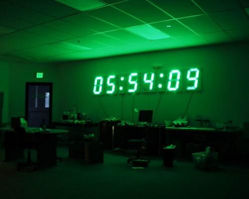
So here is the little project that grew to 12 feet. We added a GPS receiver so now we have a 12' clock that sets itself, displays hours/minutes/seconds, and is accurate to 100ns. Beat that bed side alarm!
-
Section 1 - LED Light Bar and Digit Stencil
-
Section 2 - Creating the Frame
-
Section 3 - Cutting Styrofoam
-
Section 4 - Power Over Ethernet and Wiring
-
Section 5 - Hanging It Up
-
Section 6 - The Magical Controller
The Clock Firmware is available here! C ASM HEX
Things I used -
You may want to skip over this section for now. This is just a list of all the tools that are needed:
- Hand saw
- Roto-Zip
- Vacuum (to suck up escapee Styrofoam)
- Glue Gun
- Lots and lots of glue sticks. At least 30
- Good box cutter
- Box of cutter blades - you'll need at least 10 blades
- Pencil
- Sharpie Marker
- Big burly scissors or shears
- Wire
- Soldering iron
- Heat Shrink
- Hot-air station or gun
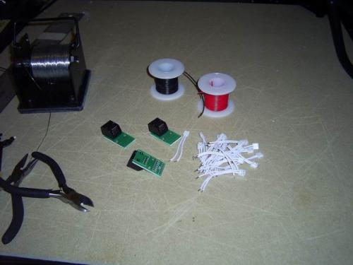
Getting the light source -
These light bars, as I like to call them, use three LEDs and run on 12V. Why use them? They come pre-packaged with current limiting resistors and nice plastic carriers. This made it easy to create arrays of a large number of super-bright LEDs, without all the hassle and labor of creating our own custom configuration.
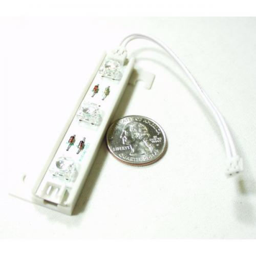
Get the LED Light Bar here!
Each stick uses about 30mA @ 12V. This is actually pretty good considering how bright they are. 30mA is a fraction of what an equivalent neon tube would pull.
It started out as just hours and minutes. Then it was obvious we needed a colon. Then the seconds were so cool that we just had to have them, so in the end, it was two colons and 6 digits. In all:
- 6digits * 7segments * 2bars per segment = 84bars
- 2colons * 2segments * 2bars per segment = 8bars
92 bars are used. If every segment was on at the same time, we would need :
- 92 * 0.030A = 2.76A
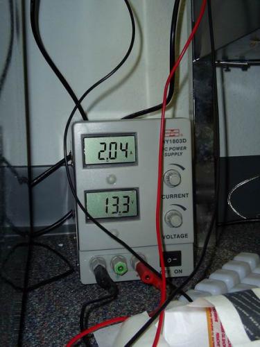
2.76Amps! At 12V is ~33Watt power supply. This is not small by any means. Come to mention it - perhaps we could use an ATX power supply... Hmm... Maybe later...
At this time, we are using a basic variable bench power supply from Mastech, the HY1803D. With an 18V 3A max output, it handles the 12V @ 3A requirement easily.
Finding the Digit to copy -
Originally I was going to simply screw the light bars onto the wall in a 7-segment digit configuration. That's where things turned south. The LED bars are fabulous! But the LED intensity is so high, it's painful to look at. So we needed to diffuse the LED light a bit and create a better shape to the light.
Shopping at the local Home Depot produced a large selection of potential options. Using a Styrene sheet of plastic (commonly used with 24x48" fluorescent panel ceilings) l was able to get rid of the 'spots' of LED light. The problem was that the styrene had to be ~2" away from the LED to get rid of the spots. I am not an optics engineer. So I decided on using 1 1/2" sheet of Styrofoam to create a light box of sorts around each set of light bars. Oddly enough, the sheets of Styrofoam came in 24x48" sheets as well. So did the 1/8" fiber board (lighter, cheaper, and easier to cut then real wood). So it was decided! The digits would be 24" tall.
Perusing the Digikey catalog for a worthy victim, I settled on the datasheet for the LSHD-5503 7-segment Red LED display.
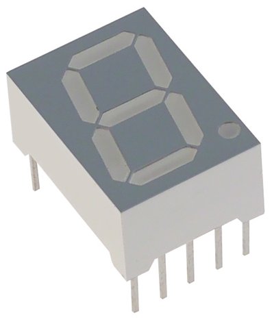
Zooming into the PDF, capturing the digit, cropping, etc. No big deal. Here is the slightly enlarged digit with segment assignments:
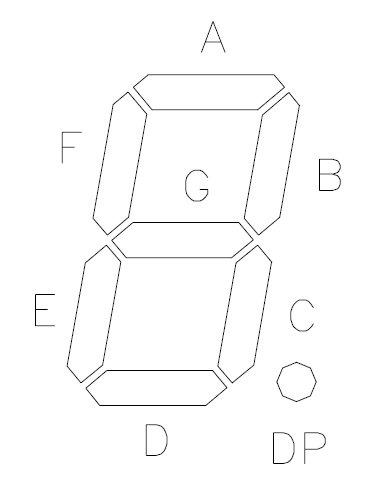
I could replicate this! So I increased the print size to 24". Using MS Publisher to create a multi-sheet printout of standard 8.5x11" sheets of paper, I taped the pages together and cut out the segments - I had my stencil!
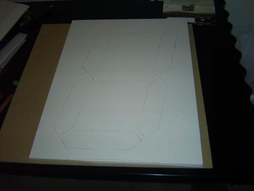
The 24" Digit Stencil
Now it was just a matter of transferring from the stencil to the various layers of the final digit.
Couple thoughts mid-conversation here - I decided to split the clock into multiple digits. This simplifies manufacturing because you just have to make the same framed digit, as many times as you need. By separating the digits, you get rid of any ugly seams in the middle of your clock (imagine the cost and hassle a of a 12' single sheet of plastic). This also simplified the wiring - 7 segments means 7 signal wires and 1 return wire (either power or ground) is needed. 8 wires - wait!! Cat5 cables have 8 wires (4 twisted pairs). Suddenly, it was painfully simple and obvious that we should split things up and use pre-terminated, cheap, easy to find, Cat5 cable to connect all these digits to the controller. Neat!
Nuther note : I used the paper stencil many times on different layers. This was a bad idea. The paper flexes and moves around causing different layer material (fiber board, Styrofoam, or foam board) not to line up. These mis-alignments are very apparent when light starts being shown through the segments. I learned only half way through to create a master foam-board stencil. This rigid stencil moves less and creates much better alignments.
So once you have your stencil created from a series of 8.5x11" sheets of paper, transfer that to an 18.25" x 24" sheet of foam board. This will now be your master stencil.
Here are how the layers break down:
-
Bottom layer (backing) 18.5x24" Fiber board
-
Mid layer - 1.5x18.25x24" Styrofoam
-
Mid layer - 0.25x18.25x24" Foam Board
-
Top Layer - 0.0625x18.25x24" Styrene
The Fiber Board and frame support the digit. The 1.5" thick Styrofoam gives us distance from the LED source to the Styrene to reduce LED 'spotting' and helps block light from one segment spilling over to another segment. The Foam Board gives us nice straight edges to the light - makes the segments look clear (getting Styrofoam to cut cleanly is next to impossible). The Styrene top layer disperses the LED light and gives the digit a white colored face.
Creating the Frame
I needed a way to cover up the ugly Styrofoam and layers. Buying an off-the-shelf 2" frame was expensive, not really available in the size I needed, and heavy. Perusing Home Depot, I found some really cheap white plastic trim used in cheap showers. This white trim came in different configurations, mainly the 'Outside Corner' configuration was the perfect fit! I could build up walls using the plastic trim to hold the thin Styrene sheets in place. The trim is also easily cut with big scissors or shears!
-
24x48" sheet of Styrene : ~$8
-
24x48" Styrofoam : ~$4
-
24x48" Fiber Board : ~$3
-
20x30" Foam Board sheet : $2
-
7' stick of shower trim : $2
So you see the yield is pretty good - we can get two digits out of the large sheets. The thin sheets of Styrene are VERY easy to cut. Just score it with any old box cutter 4 or 5 times (forget about buying the special scoring tool - doesn't work as well) - and then snap the sheet along the score. Really easy to deal with.
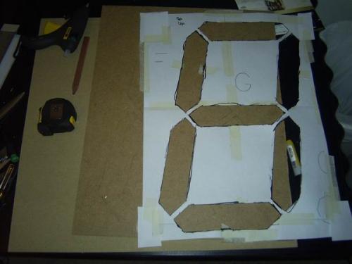
Fiber board with frame and trace of digit segments
Be sure to trace the segments onto the fiber board so that you know where to glue down the light bars.
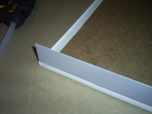
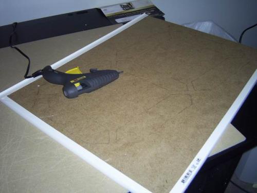
Here you can see the Styrene sides going up. We used 2" wide pieces to allow for the 1.5" Styrofoam, 1/8" Foam board, plus wires and general slack. Worked very well.
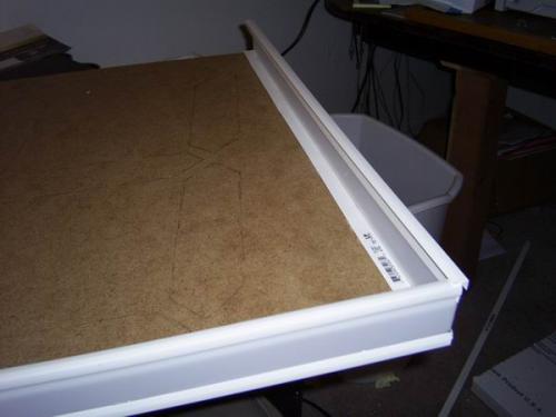
Once you have the sides up, glue the same trim to the top of the 2" walls. This trim provides the lip that will hold the top layer Styrene sheet in place.
Now the frame is done - time to create the internals!
I hate Styrofoam
Get ready to have Styrofoam everywhere. I hate Styrofoam. The little balls static cling to everything. So have your house vacuum ready and plugged in before you cut anything.
First thing, you need to cut the 48" sheet down to 18.25" wide pieces. I originally used a simple hand saw to do this. The problem is that the rough teeth of the hand-saw leave a very jagged edge where any rubbing creates more little balls that go everywhere. Only after I cut four digits did I think to use my Roto-Zip. Buy a Roto-Zip! Don't use a hand saw. The roto-zip will make things go much faster and the finished cut from a roto-zip is beautifully smooth!
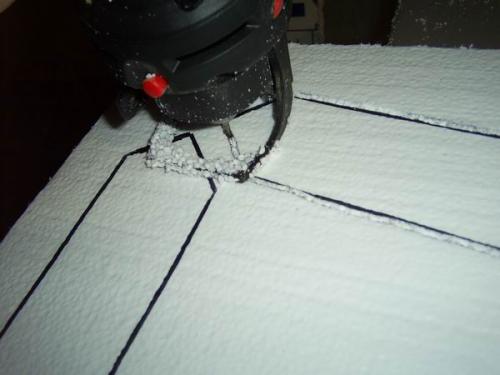
Cutting the segments out of the Styrofoam
Get ready - Styrofoam dust goes everywhere when you remove the segment cut-outs!
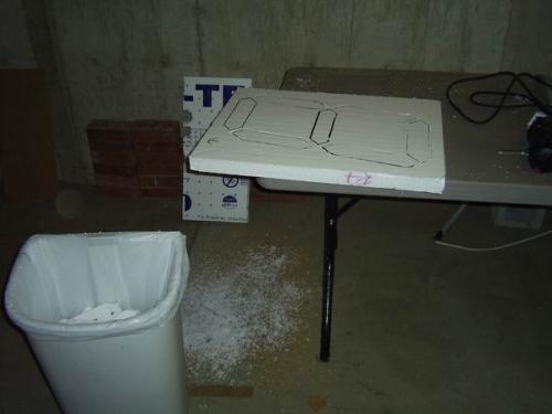
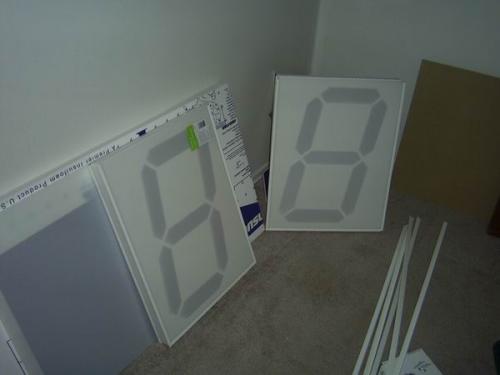
Here is a finished digit where a hand-saw was used.
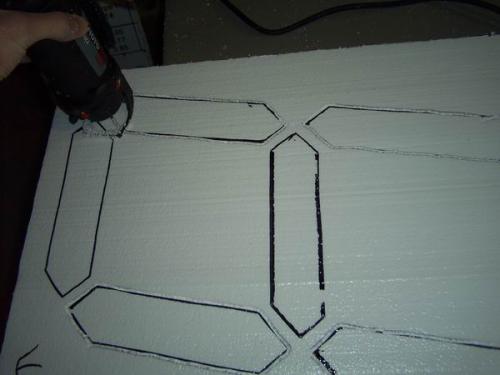
A roto-zipped digit and colon.
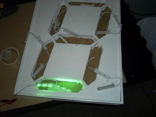
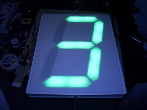
Initial light testing
Light Bars and Power Over Ethernet
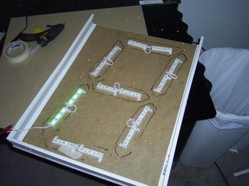
Two light bars are positioned in each segment area.
Remember to use a foam-board stencil so that everything lines up. Here you can see various outlines of what I thought would be the light cells, plus crumby Styrofoam cutting, etc. Did I mention I hate Styrofoam? You will too.
Get out your solder!
To get power to the light bars, we need to run 12V to the + terminal and Ground to the - terminal. Because every light bar comes with a connection cable, I had a large pile of extra cables. Cutting these in half and stripping them, I then soldered red and black extensions down to the base of the digit.

Be sure to remember to slide the heat-shrink on before you solder the +/- connections.
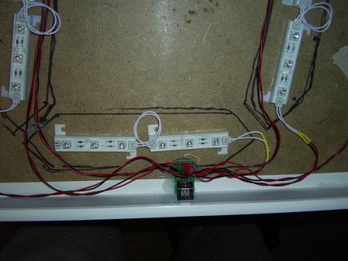
All the wires come down to the RJ45 jack. The RJ45 Jack/Board is hot-glued into place.
Okay - time to talk about the power/channel control of the system. I was pondering how I was going to wire all these segments up. It's easy for me to build a controller - it the wiring that is often the tricky part. Then it dawned on me - there will be 7segments that will each need independent power, but a common return path (ground). This means 8 wires. This means we can use Cat5 cable! Super cheap, any length pre-terminated, and very easy to add digits, colons, whatever - just plug it on!
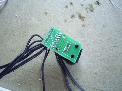
It turns out it is easier to sink large currents (IC : ULN2003A) than it is to source large currents (if this makes no sense to you, don't worry! It's not important now). So in the end, each RJ45 board in the digit has a common 12V line and 7 spots for the different segments ('A' through 'G' - see the PDF above) where the connection to ground is independently controlled. The seven channels go to the seven pins on the RJ45 jack and the 12V bus goes to the 8th pin. Notice: A small typo on the silk screen - I accidentally had two 'C's. It should read EDCBAGF - no big deal.
Wiring and drinking rum and diet dr. pepper.
You can see in the picture above, a small square hole for the RJ45 jack. This was done by tracing the jack outline through the Styrene with a pencil, scoring the plastic while it was glued in place (many times - 10-15 times), then flexing and breaking out the small piece to create the hole.
Once I had the jack soldered up, I tested out each jack before hot gluing them down. If you get +/- reversed then the segment won't work. I cut a Cat5 cable in half and stripped the end. Using my bench power supply, I attached 12V to the brown wire (pin 1) and tapped ground to the other 7 stripped wires. This caused each segment to light up momentarily. Once everything checked out, I hot-glued the RJ45 jack with lots of glue into place.
Finally! A wired digit!
Next thing we needed was a foam board layer. The Styrofoam proved to have really crumby edges which made the segments very wavy and icky looking. This was mainly due to my inability to cut a straight line with the Roto-Zip. Foam board is much easier to cut (under control) and can be cut with a box cutter/Xacto-knife.
1/4" Foam Board with the 7 segments sketched out.
It's much easier to cut straight lines using a box cutter. Be sure to re-trace any cuts that didn't make it through on the back side of the board. The pieces should fall right out.
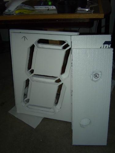
Two finished boxes
Notice the green UPC label on one of the styrene covers. I found that applying a healthy amount of 'Goo Gone' and letting it sit for 5 minutes removed any label easily without affecting the styrene.
Hanging and Testing
Excellent!
Once the boxes are complete, they need to be hung!
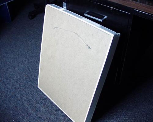
Picture Hanger Hardware
I think I paid $4 at Target for a medium box of picture hanger hardware - mainly the eyelets that screw into place and the wire is what worked well.
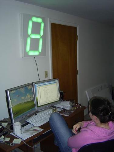
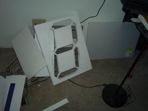
Andrea attempting to figure out why the hell I was building large '8's.
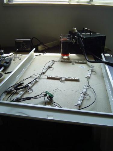
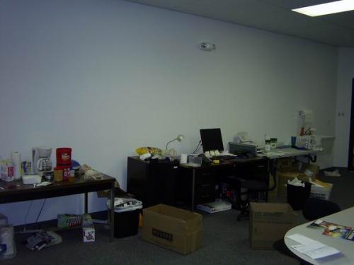
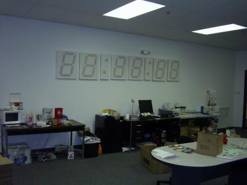
Running tests in my office.
Each digit is 18.5" wide. Each colon is 9" wide. Turns out I don't have nearly enough room at my house for testing and firmware writing. So they had a temporary stay in my office.
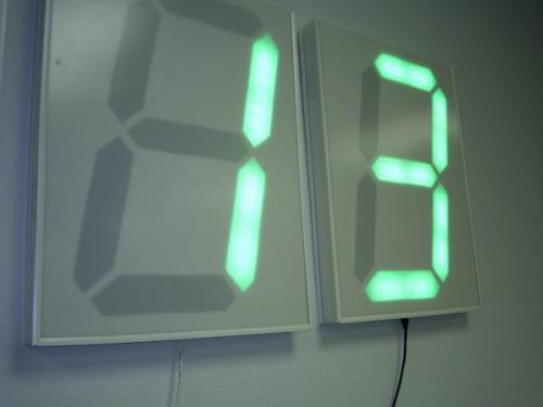
Close up shots
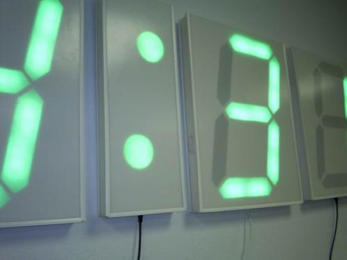
Here is the colon
I wired the colon for independent control of the dots. Why? Dunno. Maybe some day I'll want to flash each dot separately. Right now, I just flash both colons on/off every second.
Time to find a big freakin' wall -
What else did I learn doing this project? Hanging pictures is incredibly difficult to do well. The human eye loves to pick up on small differences over long distances.
The naked wall at SparkFun Electronics
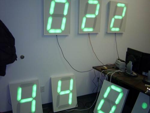
Nearly in a line!
I found out that it's really hard to hang 8 things next to each other, along the same horizontal line, with equal spacing in between each cell. Basically I measured out where the nail should be horizontally, hung the cell, then stepped back. If the cell was horribly off the horizontal, I measured how much it was off, then moved the nail. Repeat for all cells. Not ideal, but I didn't care, it was time to power the thing up!
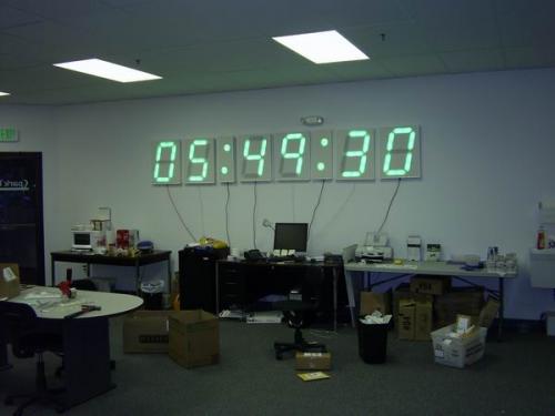
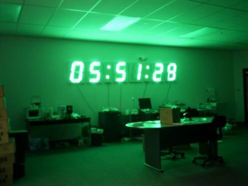
Hehe - This is going to drive Eric crazy! (His desk in the photo)
The digits are very clear, but the digital camera frame exposure helps out a bunch.
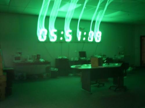
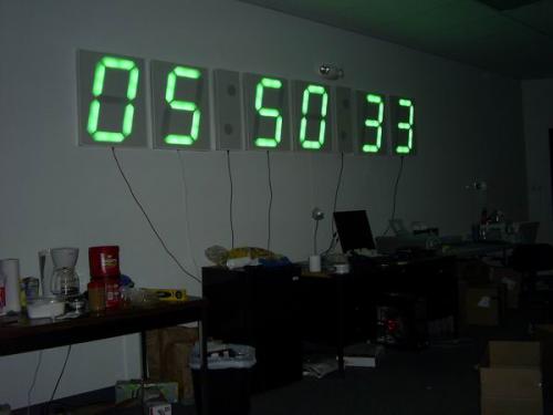
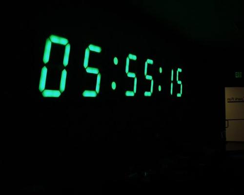
This is me trying to take pictures in the dark.
A bit better. Yes, the 12' wall clock really does make the room glow green.
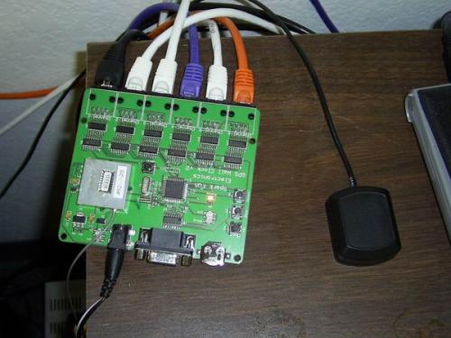
Here is the controller board with GPS antenna. It's a PIC 16F877A running some really simple firmware. Lassen iQ GPS receiver module is the big silver block.
The light bars run at 12V. There are voltage drops across the cables and circuitry so we drive out ~13V to deliver 12V to the light bars. Yep - 2 Amps!
Dark picture1
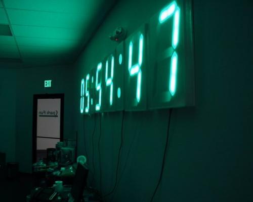
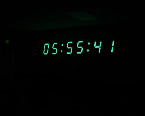
Nuther photo
Nuther photo - exactly 28 seconds later I guess...
There are a couple things that this clock does well. The control system is beautifully scalable. Powering the system over Cat5 cables makes the wiring super easy. The digits are pretty labor intensive to produce, but their design makes them easy to add/subtract from a system. Andrea had a really good idea of connecting the controller to incoming orders - we could display the sales dollar amount for the day. What about creating a clock that counted the number of seconds to St. Patrick's day? Sporting events? Number of hits to a website? Time until the next bus arrived? Time until 'beer-time' Friday? Days it will take to pay-off my college loans? The applications are pretty plentiful.
Digits are not even the limiter! We could even hook up some big freaking LED arrays. Imagine the colon dot - but in a 8 x 8 array. Ohhh - what about a massive Connect-Four game board...
Clock Control System
Wait, wait, wait! Sure, I know how to build a big digit - but how the heck did you control that much current with such few ICs and such few control lines? Ahh, I'm glad you asked. Here are some fun pointers about how to control large numbers of 7 segments LEDs.
Now if you're not a hardware person, get ready for some technical jargon.
A PIC 16F877A has quite a few I/O pins (around 32). But if you start doing the math, you see just how limited we are.
-
6 digits * 7 segments = 42 channels
Sure, we could find a microcontroller that has 42 available I/O pins, but there's got to be a better way! This is actually an age-old problem. Turns out there are chips out there! The 74HC4511 is the magical chip that takes a Binary-Coded-Decimal (BCD) input and outputs the correct pins to create that binary number on a 7-segment display.
Okay, so we go from 7 lines down to 4, big deal? There is a latch on the 74HC4511. This latch allows us to share the 4-bit bus with all the channels, and then just toggle the latch pin on the digit we need to talk to. Maybe a schematic will help:
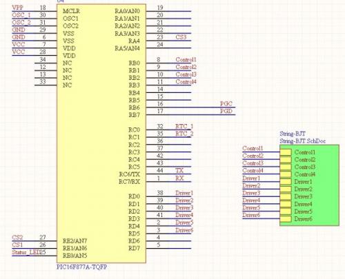
Here is the PIC 16F877A connections
You can see 4 Control lines. This is the BCD bus. There is also 6 Driver lines. These Driver lines activate the latch on each 'channel'.
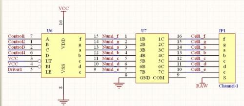
This is the circuitry for one channel
U6 is the 74HC4511. U7 is a ULN2003A. JP1 is the RJ45 jack. Just stick with me a bit longer!
The ULN2003A is a high-current Darlington array. Darling what? This IC has 7 channels. Each channel can control up to 500mA. When 1B goes high, current is allowed from the '1C' input to ground.
So when the Num1_f pin goes high, current flows from RAW, through the LED light bars in the big digit, into 1C, and then out through GND. This may seem a little bit odd at first. Maybe this will help:
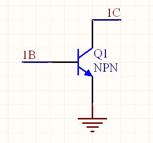
Over-simplified ULN single-channel. When 1B goes high, current is allowed to pass from 1C to GND.
This is the circuitry for one channel
Ok - so now for the chain of events.
-
The PIC parses out the GPS time from NMEA sentences coming out of the Lassen iQ receiver at 4800bps.
-
The PIC decides that the time is 6:45:33. So a '3' needs to be displayed on channel 1.
-
A binary three (0b.0011) is put onto the bus
-
Driver1 is pulled low, then driven high. Because all other driver lines are kept high, the other drivers ignore this bus data.
-
The 74HC4511 for channel 1 sees this binary number, notices that it's been latched, and then outputs the correct segments to light up a three - segments A, B, C, D, and G go high.
-
The ULN2003A detects these lines (Num1_a, b, c, d and g) go high and allows current to sink through 3C, 4C, 5C, 6C, and 2C.
-
The LED light bars inside the digit (located farthest to the right) light up the correct bars to display a three.
It's really pretty slick. The system is completely scalable. To add another 7-segment display requires only 1 additional I/O pin for another DriverX line. The PIC 16F877A could control as many as 28 digits. Have you ever seen 28 digits next to each other? How about 18" wide and on a wall? That's really huge.
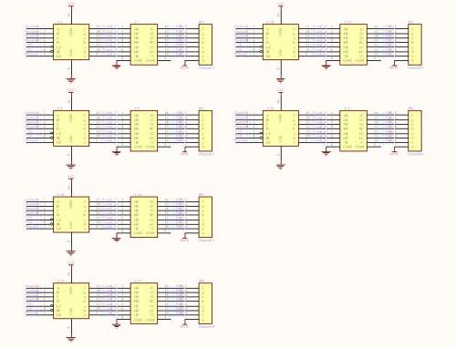
Here are the 6-channels
Here they are on the PCB. You can see a 74HC4511 next to a ULN2003A, next to an RJ45 jack for each channel.
That's it! Sorry the tutorial ended up being so long. This project took about two weeks of cutting and figuring out how to best create the digits. The firmware took about an hour and hardware layout took about three (we've used most of the basic components before). Let us know what you think.
-NES
March 19th, 2006
Is it still running?
Couldn't you use some serial-in/parallel-out shift registers to control which BCD is active? Or even better, use some stringed together instead of the BCD chips and use a reference array for the characters? 3-4 pins (serial in, serial clock, register clock, and maybe clear) for the entire system and it'd be nearly infinitely extendable.
Any chance you might make the controller available for purchase, at least an unpopulated PCB?
Tip: the cleanest way to cut a Styrofoam is heat a knife on a flame and then use it. it cuts like cake.
Model plane builders use nichrome wire heated with electricity.
Hello where can i get a printout of the Numbers and Dots at? i would like to make one for my bedroom?
I know this is a few years late, but what hit me is the styrofoam you used. If you use extruded polystyrene (EPS, "pink foam", there are no little balls, and it cuts nice and clean with a knife or almost anything. It comes in pink, but I'm pretty sure you can get it in white too. Plus, you could probably cut 1/2" sheets on the laser cutter and then just stack three of them per digit (might be able to cut thicker sheets, I just don't know.
I'm gonna have to make me one of these!
Hello everyone, First love the idea. Second I am a complete noob to the Arduino and ordering my first this week and it's the first micro processor I'll own too. But that is not discouraging me and I have a few books already purchased coming this week too regarding electronics, circuits and engineering. But anyway back to my main post. Wouldn't it be possible if not better to possible mount female RJ45 jacks on the side of the light boxes to keep a cleaner look to the setup? I know it sounds stupid but if you possibly think the center two boxes as "Home" and have three female jacks on their sides then the next pair would have only 2 female jacks then the the next set 1 then the last would be the terminating box. And it too could be scalable if you wanted to add additional boxes you could just plan for that many of required box jacks. Then just below the two home boxes you can mount your controller with all 8 lines leading out to the two boxes and then have one power supply dangling or if you could recess It in the wall and have the wall wart out below. Doing it this way you could plan better for your wiring setup and possibly make shorter 6 or 8" cat cables in white, cream or whatever your wall is colored. In reading I seen that you opted to put out 13v at 2amp due to the attenuation of the wired connection and loss of 1 volt would this then possibly require and additional .5 volt to accommodate the daisy chain effect?
Also I and not sure if anyone else noticed that the corners of the LED segments were a bit dimmer on the pointed corners? would adding a .5 to .75 inch between the the two LED bars fix this or would just adding a small bit of aluminum foil to it to create a slight reflection like they use in photography.
Great Tutorial hopefully the wife does kill me on this project if I get the courage to do it.
Any links to where you can find the styrene sheets? I'm having a hard time finding them at my local Home Depot.
Old Sparkfun headquarters... good times :)
Next time you want to cut foam with less mess, try one of these: <br />
http://www.harborfreight.com/130-watt-heavy-duty-hot-knife-66182.html <br />
and what kind of rum did you mix with the diet Dr. Pepper?
You say "30mA is a fraction of what an equivalent neon tube would pull." Actually 30mA is a pretty bright neon tube. You'd be surprised how efficient neon actually is.
No, the 30mA is what the tube draws from the HV transformer. Neon Sign Transformers actually draw several amps from mains.
Can you make me one and send it to me just tell me how much it would cost to make and ship.
Unfortunately we cannot provide custom work at this time, sorry.
Looking at the datasheet it would seem you could add intensity/brightness control by feeding a PWM signal into the Blanking Input of the 74HC4511. If you wanted to go crazy and add a 2nd (DriverX) line for each digit so each one has it's own PWM signal you could do a fade effect on digit change...
How about doing this with EL tape or EL wire segments? It would be cool if the clock blended into the wall so that if you turned it off it would be impossible to see, but using a dimmer switch, on off switch you change the brightness and it suddenly pops out!
I am not sure if I can compete with this display, but mine are also not the smallest.
http://www.youtube.com/watch?v=rkOoHor347s
nice work
can you pls put up the schematic of the board on the site???
Any chance we could get bigger pics and schematics on this last page?
I would be interested to see a schematic of some sorts, even a simplified one would be nice...
thanx!
I would be very interested in talking to you about a purchasing a similar controller. I hope that you check back here often. If you do, please post a reply and lets talk. mikem@uesomaha.com
I think you could have avoided all the EPS dust and got a cleaner edge if you had used a hot wire foam cutter instead of a saw to cut it.