
High Voltage Ringer
The Port-O-Rotary has a certain degree of stand-alone sweetness. It harkens back to an era of simplicity, while freakishly juxtaposed with cutting edge tech. If you ask me, that's a good mix.
The one thing the phone lacks is that classic cardiac arrest twin bell ringer. Why does it lack this? Because the original ringer runs on 80VPP! What now? Can this be made to work at 3.8V? I'm happy to say that the answer is "yes".
Words words words, I want to hear it ring! ringer.mp3
How We Do This...
So we've got 3.8VDC and we want to make a really big AC signal. Where do we start?
The first thing is to make the 3.8V into a larger DC voltage. We do this with a boost converter. Many flavors of boost converter will work, but we happen to be using the MC34063A from ON Semiconductor.
Once you've got the big DC voltage, you run it through an H-bridge. The idea here is that you're going to be making two big square waves that run 0 to +V and are 180 degrees out of phase, OK? It's a push-pull sort of thing. Now, we could also have done this with 4 transistors, but we have H-bridges on hand to use as motor drivers, so there you go. Specifically, we're using the TI SN754410. When referenced to one of the two square waves, you end up with a signal that goes +V to -V. It's getting bigger...
The last thing we do is to tune the inductor on the ringer with a cap, making a resonant circuit at the ring frequency (which for my testing was 22Hz). This little trick substantially boosts the current in the inductor, and that equates to more pulling force on that little hammer in there. Is it loud? I can't hardly be in the room with it anymore.
Here's the schematic for the prototype:
The values may change as we optimize, but these work pretty well for now. If it's not completely readable, the parts list is as follows:
- R1 47K
- R2 1K
- R3 180 ohm
- R4 0.25 ohm (used four 1 ohm, its' what we had on hand)
- C1 0.1uF
- C2 3.3uF, 100V (this should probably be bigger)
- C3 1000uF, 63V
- C4 1000pF
- C5 0.1uF
- C6 1000uF, 10V
- L1 150uH, "high current"
- D1 1N5822 Schottky
- U1 SN754410 H-bridge
- U2 MC34063A
Some Noteworthy Points
The boost converter works by comparing the voltage at pin 5 to an internal reference of 1.25V. Since there's no current in the line to pin 5 (it's a comparator input, after all), you can back out what the output voltage is by Ohm's Law...60 volts! Well, ours won't do that, but it does go to about 54V without a load. That's a lot, man, but it really won't drive much (more on that later). To help carry the burden, we use some big caps on the output and input to the boost converter. When the ring sequence starts, C3 starts to drain fast. By jacking up the value of C4, we make the charge reservoir bigger, so that when C3 starts to go down it'll draw on C4 to take up the slack. When the ring sequence ends, C3 and C4 charge up again.
If you're not H-bridge savvy, it's pretty simple. VCC1 drives the logic in the chip, and VCC2 is the voltage that goes out on 1Y and 2Y based on the signals at 1A and 2A. Each of these signals is a 0 to +V square wave at 22Hz (from a PIC), 180 degrees out of phase with each other. Nothing to it.
The last thing to note is C2. That's the tuning cap for the ringer inductor. Now, there are two coils on the ringer...well, it's a transformer, isn't it? What do they do with a transformer there? Beats me, but that presents us with a choice. For your reference:
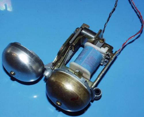
You might be looking at something similar. They don't come twisted like that, I just checked all the wires with an ohm meter and then twisted up the ones that were related to each other. One coil measures about 990 ohms, the other measures something over 2K. I went for the 990 because I wanted more current to drive the hammer. I didn't have any kind of fancy inductance meter or impedance analyzer, so I ballparked the inductance by making a signal generator with my PIC and splitting the voltage over the coil and a resistor. When you can measure the same signal level across the resistor and the coil, you know that the inductive reactance equals the resistance. Then you can back out the inductance from
L=(reactance)/(2*pi*frequency)
It's quick and dirty, but it got me within an order of magnitude. And as you might guess, it's not a small number (around 4H calculated). Once you get the ballpark value, you manually tune the circuit with various cap values until it resonates. This is done with an O-scope measuring from the point between the cap and coil to ground and changing the cap value until you maximize the voltage seen across the coil. Well, it's a bit more complicated than that. The signal you'll see there when it's resonating is mostly a sine wave, but it has a discontinuity when the H-bridge switches. In simple terms, it sort of looks like a sine wave with a "shark fin" riding on top of it, like so:
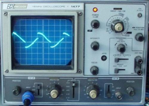
When the resonant frequency of the tank circuit is the same as the switching frequency, that shark fin will be right on the peak of the sine wave. Mine's a little off as you can see, but it'll do just fine. And it'll be a big signal. Remember that we start with a signal from the H-bridge that's about 108VPP (which ideally would be enough to get the job done, but the boost converter by itself can't drive it - more on that coming up). At resonance, I think I measured something like 180VPP+ at the beginning of the ring. The signal pictured is a bit past the start of the ring cycle and looks to be about 130 to 140VPP at 50 volts per division on the scope.
Once you get it tuned up, you can figure out what the actual inductance is by
L=(1/C)*(1/(2*pi*frequency))^2
In my two cases (I had two ringers), that came out to be about 15.9H. At 22Hz, they tuned up nicely with a 3.3uF cap. I don't think anybody will actually have to go through my method to make this work. Just use a 3.3uF cap and the 990 ohm coil and see how it goes. You may have to play with the spring pre-load on the ringer a bit to optimize it. You decide.
So here's the thing: when you series tune a resonant tank circuit, the reactances cancel and you end up with the DC resistance of the coil as the whole load, which in our case is about 1K. What does that mean? Well, where the boost converter is concerned it means 1K across around 50V, and that's 50mA. In a perfect world, power out equals power in (efficiency=1). We're not even in the same time zone as that place. Even if efficiency were 1, we'd have to draw half an amp at 5V to source 50mA at 50V. As it is, our efficiency is probably WAY off that because we're operating the boost regulator at the far end of it's working spectrum (it can't even make the 60V we're asking for). So it's anybody's guess as to what it's got to draw to make it work (one of my measurements showed a draw of 270mA, but that will vary with time). That's why the caps on the converter are as big as they are. In spite of their size, however, the converter output voltage is seen to drop from 54V to about 41V during a ring cycle. That's OK, though, because once that little hammer is moving it doesn't take as much to keep it moving.
Mechanical Aspects
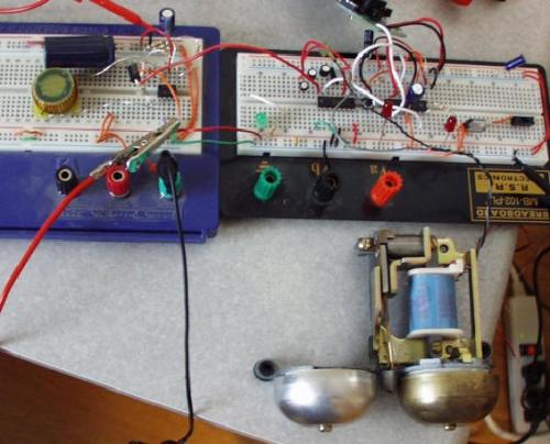
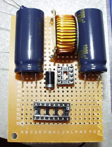
Initial breadboarding to see if this had a hope of working. The boost converter is on the far left (the little chip with the huge inductor). Lots of bare wires in there. Hopefully anyone trying this will be cleaner about it that I was.
Initial attempt at a prototype layout. There's not a lot of room inside that bakelite case, but there's enough for this.
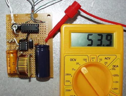
The finished product, powered up and showing 53.9V with no load. The large parts are hot-glued down to the perf board, as are the outgoing leads to provide some strain relief.
In the end, I'm surprised that it works as well as it does. Ultimately, the boost converter will have to be disabled when there's no ring to perform because it's a power hog and not well suited to run off a battery for any length of time. An overly industrious person might also try wiring up the two ringer coils in parallel and in phase to get even more noise out of the thing, but I think it's annoying enough as it is.
As usual, let us know what you think.
-PDD
March 4th, 2005
I just realized, 10 years later. why the H-bridges blow: You need a flyback diode across the ringer because a ringer is an inductive load.You're getting high(er) voltage spikes that the H-bridge isn't able to handle. Try a 1N4007 or similar diode.
eBay DC converter
Next step is to order a cell phone shield and build this: http://www.stavros.io/posts/irotary-saga/
SN754410 H bridge explained
You supply two low voltage block signals; one to 1A and one to 2A. The block signals are 180 degrees out of phase. The block signals are relative to GND. By supplying a large voltage on VCC2, outputs 1Y and 2Y will provide a high voltage symmetrical block wave like so:
STEP 1 - You can program an Arduino to generate two 5V 22Hz block waves 180 degrees out of phase like so:
You should now see the LED on pin13 flash at 20Hz for 1 second twice in rapid succession followed by a 1.5 second pause. pin12 carries the same signal, but 180 degrees out of phase.
STEP 2 - Build the SN754410 'push-pull' symmetrical block wave circuit
Simply use VCC = VCC1 = VCC2 = 5V from your Arduino for now.
STEP 3 - DC/DC converter
Buy a 12V in 30V-60V-90V out DC-DC converter from eBay to provide a high voltage to VCC2 instead of the +5V DC to boost the output signal on 1Y/2Y.
STEP 4 - Increase VCC2
Finally replace VCC2 with a higher DC voltage not exceeding 35V. 1Y/2Y signal amplitude should increase accordingly.
Note: SN754410 is rated to 35V DC as stated in previous comments. Order more than one SN754410 if you are going to attempt to build this circuit.
I was able to make it work just using the SN754410 + eBay DC converter (measured output of 50V DC) + Arduino without any passive components (i.e. capacitors) at all. Just keep your finger on the SN754410 to feel if it is getting hot or not (and connect a heatsink if need be).
Every time he mentions C4, he's actually refering to C6. C4 the timing cap has nothing to do with what he's talking about.
@ PDD: You should have done a little research into how mechanical telephone ringers are typically wired. The two windings (on older phones, actually two separate coils) are usually connected in series (and for this layout, in phase). Connecting them that way would give you more "bang" for your power-input buck, and reduce the demands on your ringer circuit.
I built this ringer circuit and it worked a treat. Only problem is that it kept blowing the H-bridges (and PICs). I think this is due to the rated voltage of 36V, as jwr pointed out, not sure why the PICs kept blowing. In the end I bought 10 of each, but gave up after blowing a few more. I am going to redesign the circuit so that it outputs 36V and maybe put some protection in for the PIC. Actually it didn't start blowing the components until I soldered it all up onto Veroboard, maybe I made some minor error somwhere.
The SN754410 is rated up to 36V — it seems you're way over the specs.
Any and all help is appreciated, because if I am not mistaken there needs to be some sort of signal on 1A and 2A on the H Bridge, however if it is just coming straight off of the header, I am not seeing where that signal is coming from unless it is tied to VCC or the boosted outputs?
Anybody have any info on the above questions I asked, I have all the parts, just curious about the 4 pin header and what the two inner connections to the H Bridge actually do. Thanks a lot!
If I just wanted to have the voltage output as a DC signal, would I just need to omit the H-bridge section of the circuit and complete the bottom half of the circuit? Thanks! Good tutorial, I just stocked up on these ON boost converters from Newark.
any chance you'll sell the pcb with a parts list?
I have a need for a 26VAC power supply that can provide "10VA" at 400Hz and run off batteries. It's an old standard for aircraft avionics.<br />
I bought an inverter with these specs, but it cannot source enough current. The output on a scope looks similar to the one in this project, so I thought one of these ringer units might work for me. Or instead, is there a simple way for me to add some transistors to the output of my inverter to boost the current to 10VA? I'd really appreciate any ideas/comments.<br />
So do I still need my controller to alternate the power between the two pins on the H-Bridge in order to make this work, or does the circuit itself handle the oscillations?
What is the purpose of C5 in parallel with C6?
decoupling cap(filter any noise on VCC to gnd)
Schematic:
http://www.sparkfun.com/images/tutorials/high_voltage_ringer/ringer1.gif
Hello,
please share the schematic. It's a nice project.
Thanks
Please share the schematic.
Thanks for the tutorial.
cool. but where's the schematic?!
ringer circuit lost ....