
Foamware
What the heck am I going to use a tilt sensor for?
How about detecting the tilt of a plane? We fly RC gliders in our free time and someone decided that it would be really cool to see "what a right turn looks like."
The tilt sensor about to be loaded up
For your viewing pleasure:
1 - Background
2 - Foamware Setup
3 - Software Setup
Forget all this babble - show me the results!
plane1.xls - Looks like a few good turns
plane2.xls - Blah (No good)
plane3.xls - Blah
plane4.xls - Blah
plane5.xls - We snagged a lot with this one!
longflight.xls - I like we just left this one running (really big)
The Plan -
We wired up a tilt sensor, tested the output to make sure that the PIC could get the data and started dreaming up some applications. Of course we already had this experiment planned before we ever had the tilt sensor in our hands! We wanted to see what the tilt information looked like for a RC glider. This was the perfect test bed because the plane itself is made of styrofoam (good protection) and tape (quick modifications). The tricky part was getting that information to the eager geeks on the ground.
We considered recording the flight data to an eeprom. The problem with eeproms is that they have relatively little storage room. We would also not be sure that the data was good unless we downloaded it and viewed it. If something was wrong you would not know if until you had pulled the plane apart and wired into the eeprom. This was way too cumbersome. A breezy day for a good test flight is hard to come by - we couldn't be tweaking stuff on a whim and expect to be able to fly the next day.
The best solution is to view the data is real time with a wireless link!
On to the Foamware Setup
The all too simple wireless links!
Wireless is no longer something to be afraid of! In fact, it is so incredibly simple, you'll wonder why you haven't attempted it before.
If you are afraid of flying RC planes because you think you might crash it - get foamie! These Styrofoam planes are indestructible.
For your viewing pleasure:
1 - Background
2 - Foamware Setup
3 - Software Setup
We used the 433MHz TLP-A and RLP-A. The best way to describe these wireless modules is a black box - I don't have a clue what happens in the air, all I know is that what I put in the transmitter end is what comes out at the receiver end.
The transmitter has four connections - Power, Ground, Antenna, and Data. Whatever is on the data pin (logic high or logic low) is exactly what will appear on the data_out pin of the receiver (up to around 4800 baud). The only catch is that there is a heck of a lot of noise in the unlicensed bands. So if you simply power the receiver and watch what is going by in the air - it's a lot of junk. You will need to filter the received data somehow. The way we did this was to monitor the data_out pin of the receiver and when you see the 'start' byte of your specific protocol - that's when you store the next couple bytes. Take a look at the protocol later on - it's very simple.
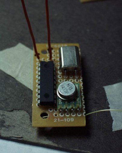
The module
We tapped directly to the glider's 4 cell battery pack. Yea, you should throw a voltage regulator on there but there are a few reasons why a voltage regulator is a bad idea.
1) The battery pack is a nominal 5-6V. Not even enough surplus voltage for the regulator to do anything. A good rule of thumb is a minimum of 2 volts overhead voltage above the rated voltage of the voltage regulator (I used the word 'volt' 5 times in that sentence). If you want 5V out of the regulator, you will need at least 7V going into the regulator.
2) The transmitter's performance is directly related to the supply voltage. Even the extra ~1V coming in raw form from the battery pack can have a positive impact on transmission range.
3) Less weight - we like to do things simple (and a little dirty). By eliminating the voltage regulator, the whole unit could be kept very small.
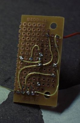
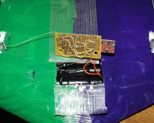
Back side
A quick job of connecting all the major connections. We used a 16F628 operating at 20MHz. We could have run with the internal 4MHz but by increasing the speed of the processor, a higher counter could be found - thus a more resolved reading (better precision - not better accuracy).
The near final package - missing the ADXL
It was a very small package. Two of the RB Port pins (on the 16F628) were connected to the X and Y pins of the ADXL. The TX pin of the 16F628 was connected to the DATA pin of the transmitter. So by polling the PWM signals from the ADXL, embedding those values into a string, and sending that string of numbers out the UART at 4800 baud - we could communicate the tilt values very easily (yea right) to the 'base' station.
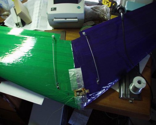
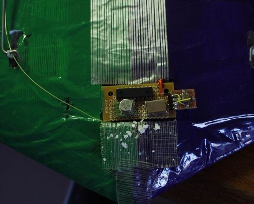
Finding its home inside a Zagi Foamie
This is a nice shot of the plane - nothing is simpler, cheaper, or easier to learn on than a Styrofoam Zagi wing!
Here you can see the 16F628, the transmitter, the 20MHz crystal, the ADXL sensor, and the yellow wire is the 30-35cm antenna. The entire unit was plugged directly into the glider's battery pack (4 AA cells).
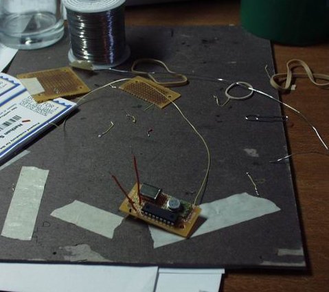
Connections to power
Once the whole thing was connected to power we checked to see that the module was correctly broadcasting the ADXL data. We then taped the module in and threw the thing off the hill.
On to the Base Station Setup
The geeks on the ground.
The plane is talking - we need to listen. The base station receives the incoming info and posts it to the laptop screen. The trick is ignoring all the other noise coming across the line.
For your viewing pleasure:
1 - Background
2 - Foamware Setup
3 - Software Setup
The base unit was very basic. It was composed of a receiver module, a 16F628, 20MHz xtal, a DB9 serial header, and another battery pack. We used a very simple protocol (I guess you could call it that). The plane would transmit a series of 4 bytes. Every output started with a known start byte - 0x4D for instance. When the base 16F628 detected this byte (using the UART interrupt) it would record the following three bytes. If the 4th byte (third following byte) was the correct known stop byte (0xD4 for instance) then you could assume that the data was good. The PIC then stored the good data into an array. An example of a received string:
0xCC 0x23 0x44 0x4D 0x44 0x54 0xD4 0xFD 0xCB
We would want to ignore everything except the middle two bytes between the start and stop bytes. These two bytes represent the counter values found for the X and Y axis pins and would be recorded into a special data array of good timer values. In the main loop this good_data array would be outputted serially (bit banged really) over another pin to the DB9 header. This connecter was attached to our buddy's laptop and we could watch the stream in real time under hyperterminal.
Hyperterminal has the cool feature of capturing to a file (yea, it's not really that cool, but it's REALLY helpful). So the person flying the glider would announce that they were 'about to take a right turn'. The person on the laptop would start a capture - as soon as the pilot states the turn is completed, the person on the laptop would try to end the capture as quickly as possible to limit the data to only that turn. This is what we tried to do but it was a bit difficult to respond that quickly. We where never sure if we had captured one turn, or part of a few. It made the data a bit difficult to interpret.

Dah, is that noise? Or um, sure - that's a left turn.
The following excel spreadsheets is what we captured. This is real-time, real-world data folks so things may look a bit messy. Hmm. On second review, I can't make much of it anyways. The counter values were a little buggy. You can make out the transition of a turn very well - but exactly what a 'right turn' looks like is up for debate. In the end, we are going to have to re-fly the glider and get some new data. As if I needed a reason to go fly!
plane1.xls - Looks like a few good turns
plane2.xls - Blah (No good)
plane3.xls - Blah
plane4.xls - Blah
plane5.xls - We snagged a lot with this one!
longflight.xls - I like we just left this one running (really big)
Comments 0 comments