Enginursday: Introducing the MicroView!

We're really excited about the MicroView -- a new Arduino compatible board with an integrated display! Check out why...

Favorited Favorite 1

I'd like to use my Enginursday post to chat about a new project our SparkFun team is working really hard on these days -- something I'm super-excited about -- the MicroView!

ReplaceMeOpen

ReplaceMeClose

The MicroView is a collaborative project between SparkFun and our friends JP, Marcus and Maddy from Geek Ammo, the team behind the Ninja Blocks and Little Bird Electronics.

The MicroView, like many a brilliant product, began as a prank. When teaching Arduino classes, Marcus was frustrated by the disconnect between what's going on inside the Arduino and the limited outputs a student can actually visualize. Aside from staring at hypnotizing, scrolling lines of the serial monitor text, there's really no easy solution to show the data in your Arduino. To first combat this, they came up with the Magpie -- an Arduino-compatible board with LEDs on every output -- but Marcus asked JP if he knew of an even better solution. To which JP responded with:

OLEDuino

*OLEDuino not actually a thing.

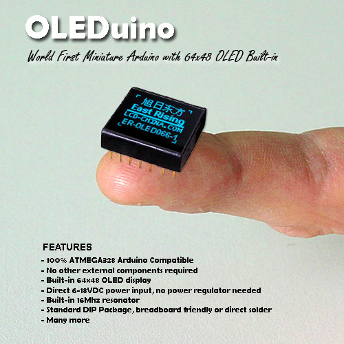
A completely fabricated, photoshopped image of a chip with a built-in OLED display. JP got Marcus hook, line and sinker, and Marcus instantly wanted it! When finding out that he couldn't purchase this awesome new product, Marcus, not to be let down by JP's prank, convinced his team to make the MicroView a reality.

MicroView lit up with SFE Flame

The Geek Ammo team has put the MicroView up on Kickstarter, and we've been working with them along the way, helping where we can with PCB design, part sourcing, manufacturing, and eventually reward fulfillment (this ain't our first Kickstater rodeo). Check out their Kickstarter video!

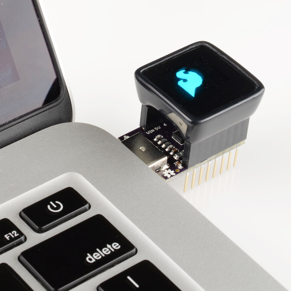
What's awesome about the MicroView is its utility for electronics beginners and experts alike. For beginners, the MicroView is one of the easiest-to-use Arduino platforms available -- it's perfect for anyone looking for an education in electronics, programming, or Arduino. The integrated display really helps to visualize what the microcontroller is doing (you might say it gives you a view into the microcontroller). The MicroView will even ship with built-in tutorials to help folks get started; and the Geek Ammo team has built a set of cross-platform, interactive tutorials that teach you how to create 11 different circuits.

uView attached to a photocell

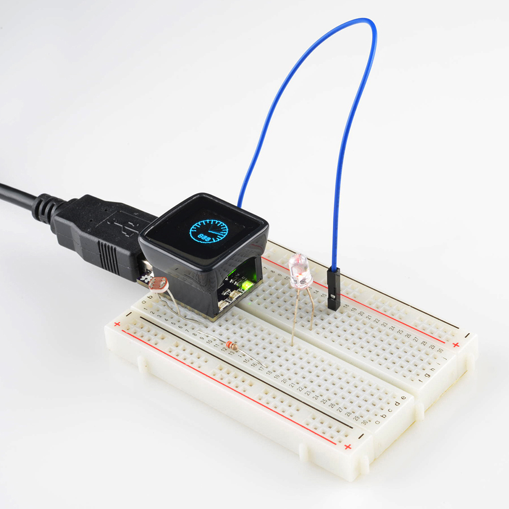
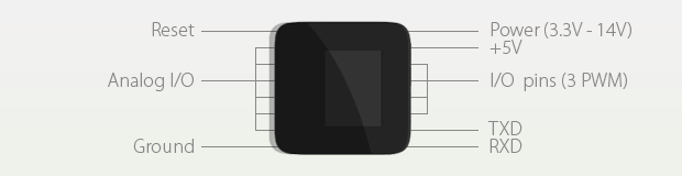
The MicroView is also great for experienced electronics users. It uses an ATmega328P chip -- just like the Arduino Uno -- and runs at 5V/16MHz. It breaks out a dozen I/O pins, including six analog inputs (A0-A5) and 3 PWM outputs.

uView pinout

The projected pinout of the MicroView.

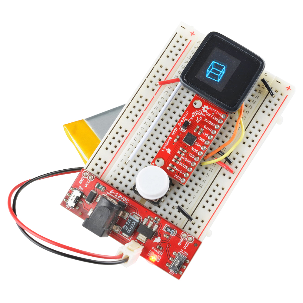
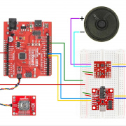
I'm personally excited about it because, by using it as a testing and rapid prototyping platform, it's going to make my job easier. It'll be especially awesome for testing out motion sensors, GPS modules, wearables, or anything that requires mobility. I've already built up a jig to use it to test our new LSM9DS0 9DoF Breakouts:

Using the MicroView to test the LSM9DS0

And, of course, the MicroView should have a bright future as the center-piece of finished projects. Smart watches, geo-cache sniffers, mobile breathalyzers...you name a project, I'm sure we'll see the MicroView integrated into it soon.

Right now we're in a prototyping stage with the MicroView. We've got some functional boards and enclosures, and (not to brag or anything) I've been lucky enough to get to start playing with them testing them out. They're awesome! If you want to get in early on the action, go back it now on Kickstarter!


Comments 37 comments

  • Blacklab1 / about 10 years ago / 3

    My only concern is how long will the display last. I have equipment in my house that uses OLEDs and after a year of uses, you can barely read the display.

  • JohnGalt / about 10 years ago / 2

    No SPI broken out..... What about I2C (Preferably hardware based I2C)?

    • kgrr / about 10 years ago / 1

      The SPI interface appears to have been dedicated to the display. Pins 11, 12 and 13 are nicely tucked under the glass lid and OLED. Another I/O pin is normally used to chip select another slave SPI device. It looks like pin 4 is being used to turn on/off power to the display.

      pin 11 - MOSI pin 12 - MISO pin 13 - SCK

    • kgrr / about 10 years ago / 1

      Pins 2 (SCA) and Pin 3 (SDA) look like I2C bus connections. Do you know if the wire library is supported? The MCP23017 ‑ i2c 16 input/output port expander would definitely create lots of I/O pins for more complex projects.

      • kgrr / about 10 years ago * / 2

        Yes the wire library is supported.

        In the sparkfun forum for MicroView, I have posted a couple of my projects that use the I2C interface. MicroView Projects

      • M-Short / about 10 years ago / 1

        The microview is based on the ATMega328 meaning the I2C lines are on A4 and A5.

        • kgrr / about 10 years ago / 1

          The A4 and A5 lines from the ATMega328 are brought out on MicroView on Pin 2 - SCL Pin 3 - SDA

  • ameyring / about 10 years ago / 2

    The videos and pictures show MicroViews running without attached components (on fingertips). Is there a battery hook-up or is it just an image to show the size and the possible graphics?

    • Member #25864 / about 10 years ago / 1

      There are micro-wires going to a battery that was taped to behind my arm.

      Cheers,

      Marcus

  • ME heat o nator / about 10 years ago / 2

    world's coolest mood ring!

  • Kamilion / about 10 years ago / 1

    Awwwww... I was REALLY hoping this might be a little better than a 328p stuffed inside... No ATMEGA32U4? C'moooon! Leonardo is an Arduino too! No need for classics like the 328p when the 32U4's around... ... Right? Riiight?

  • JohnGalt / about 10 years ago / 1

    How about A MicroView Mega, with more pins broken out...... Say in a 40 pin DIP form factor. This could be a really nice rev 2.0

  • JohnGalt / about 10 years ago / 1

    anyone have a link to a complete pinout and schematic?

  • GordieGii / about 10 years ago / 1

    This looks great! I love the necklace here: https://s3.amazonaws.com/ksr/assets/001/729/494/a53a8d25d4579ed7322a7c33b5bc3d40_large.gif?1394454823 I can't imagine wearing one though, with the pins poking and scratching my neck. Maybe it would be better with female headers. Double headers (like these: https://www.sparkfun.com/products/117 ) could be inserted to put it in a bread-board. For small projects male jumper wires could be inserted. Perhaps the female headers could be parallel to the face so jumper wires could be inserted while it is laying flat on the table and right angle headers inserted for bread-boarding.

  • tim7 / about 10 years ago / 1

    This fantastic. In fact the Microview is so sleek and compact that it's almost a pity to attach anything to it. Even a minimal PCB and battery is going to make it a lot bigger and uglier.

    What I'd love to see is is an all-in-one Microview II with built-in battery, perhaps a couple of buttons, and no external pins (perhaps the case could be made so that the pins were easily accessible if needed, say by drilling a hole or two).

  • Can't wait to see these in production. Are there any plans for a larger version, with more/all of the pins broken out? Are there any other versions being planned ...period?

  • nsayer / about 10 years ago / 1

    I don't know if it's of any interest, but I designed a thing I call LCDuino as a response to the same issues. It's what you get when you mash an Uno and an AdaFruit RGB backlit 2 line LCD shield together and cram them into an 80x36 mm space.

  • tetsujin / about 10 years ago / 1

    Is the SSP broken out somehow? (To allow rewriting the bootloader, at least...) The pinout shows four digital I/O pins, of which three are PWM. That means the SPI port isn't (apparently/entirely) broken out as two of the lines (MISO and SCK) are neither analog inputs nor PWM outputs. Is there an alternate means of accessing the SPI port?

    • jimblom / about 10 years ago / 3

      Unfortunately neither SCK, MISO, or MOSI are accessible when the board is enclosed -- just not enough room to break them out.

      They will be broken out on the PCB though (we'll need them to program the ATmega's in production). On our prototypes they're broken out to a small 0.1"-pitch, un-populated header. It's not too too hard to safely remove the cover from the enclosure to get to the PCB, so it'll definitely possible to access the SPI port.

      • Jimb0, that is weird, i'm a backer since the begging on the kickstart campaign, and i'm watching closely the discussion, and JP said in one comment that the enclosure would be "hard" to remove. Nevertheless MicroView is a awesome product and i'm anxious to get mine!

        • jimblom / about 10 years ago / 1

          JP's right. It's definitely designed to be kept in place, there are protruding snaps on opposite edges of the cover that hold it solidly into place.

          For the hacker-types, though, it's do-able (I've had some practice this week :), but it is bound to leave some scuffs. You'll see when you get yours (thanks for backing!), but you can wedge a thin flathead between the screen and enclosure to pop it off.

      • tetsujin / about 10 years ago / 1

        Neat. Seems like a good compromise given the constraints of the design. Are there any other additional I/O lines accessible internally? I feel like a device like this really needs a pushbutton or two, if I can find a place to add them...

        • jimblom / about 10 years ago / 1

          Nothing else easily accessible as of now (but soldering wire-wrap wire to TQFP pins isn't too hard, right?!). It's a tight layout, but we'll see what else we can fit on there!

          • tetsujin / about 10 years ago / 1

            Is the display wired to the SPI port? If not then I could wire up a pushbutton to that - assuming I can find a place to put a pushbutton. :) If nothing else I'd expect the SS line is probably free...

            • The display is on the SPI. :) I'll try to follow the Limb0 tip and solder a tinny wire directly to the atmega pin.

              • tetsujin / about 10 years ago / 1

                The reason I thought the SS line would be free is 'cause when you're programming the ATMega you wouldn't want the display to think you're talking to it... So I would expect some other ATMega I/O line is being used for the display's slave select, and thus the ATMega's SS line is probably free. 'course I could be wrong. Could be they're programming the boards without the display connected or something.

                • anyhow... the schematics are posted here....

                  http://bit.ly/1g73lXm

                  You can see that SPI is being used to the OLED display :)

                  • JohnGalt / about 10 years ago / 1

                    Got a better link, this one seems dead.

                  • tetsujin / about 10 years ago / 1

                    Yes. There was no question of whether the SPI port was connected to the display - the only question was which lines of the SPI were used and which weren't. Given that a lot of displays are write-only, there seemed a fair chance that the MISO line, accessible on the ISP header, might not be connected to the display. But as it turns out the MISO line is connected to the display's reset line. Oh well. I guess it's back to QFN soldering if I want to hack this thing.

        • XLT_Frank / about 10 years ago / 1

          I agree.

          What about a right angle header in the crotch of it to breakout the SPI?

          What about making the surface touch capable? In other words, the whole surface acts like a pushbutton?

          • tetsujin / about 10 years ago / 1

            Personally I'd rather have the simplicity a good old fashion button or two, if there's some input added to this thing in the future. But yeah, touch sensor would be a cool alternative, and possibly more compact.

  • SXRguyinMA / about 10 years ago / 1

    Cool except for the OLED. It will be fun till the OLED's start fading and you can't see anything >_<

  • I'm right there with AgustinGS. I jumped on this bandwagon early, and I'm thrilled to see the ridiculous amount of backer funding they've already generated. And I, too, wish I had a spare dump truck full of money to trade for a dump truck full of MicroViews!

  • AgustinGS / about 10 years ago / 1

    Yup, I agree, and have already contributed. love the idea of it, I just wish I had tons of money to but a whole lot of them! Does anyone know if there'll be a product page with a "getting started" section? I highly doubt it'll just automatically start displaying my sensors data..

    • there will be more documentation than you know what to do with. Jim can comment further, but there's already a lot of good documentation and libraries to make it pretty easy to use. Once the dust settles from the kickstarter and things start shipping, we'll have at least a basic tutorial to guide you through using the microview.

      • JohnGalt / about 10 years ago / 1

        So, when will they start shipping? When will spark-fun preorders go up?

Related Posts

Recent Posts

Open-Source HVAC?

What is L-Band?

Tags


All Tags