Enginursday: Getting Started with LTspice

Learn the basics of SPICE simulation with Linear Technologies' free LTspice program.
When I think back on all the tools that helped me understand electronics, verify homework solutions and even help design products, LTspice is still at the top of my favorites list. LTspice is a free program from Linear Technology, hence the LT prefix in the name. SPICE is actually an acronym standing for Simulation Program with Integrated Circuit Emphasis. While there are many LTspice tutorials out there, SparkFun has been an entry point into electronics for many people. The motivation behind this post is to get LTspice in the hands of new users who wouldn't know to search for it. And hopefully I'll provide some new insight for seasoned veterans of the program. If you have questions, comments, links to other tutorials, example schematics or simulations, head over to the SparkFun LTspice Forum. I'll be dumping all my circuit examples, homework examples and personal projects there and answering your questions in that forum.
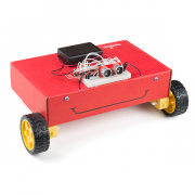
A year ago, my first assignment as an engineer for SparkFun Electronics was to redesign the Electret Microphone Breakout Board with the constraints that I could not replace the operational amplifier. This meant I could only change the values of the passive components in the circuit. I used LTspice to simulate the behavior of the new design so I knew I was getting the best performance out of that part. I used the Electret Mic circuit as an example to show how to import third-party models into LTspice.
LTspice is a great tool --- not only to simulate a design, but for teaching circuits and general concepts. When I need to describe how AC to DC converters work, I use a full wave rectifier circuit slowly pieced together showing the simulated waveform differences between an AC signal, half wave rectification and finally the DC signal after full wave rectification and smoothing. Even if you don't have an oscilloscope, you can still get a pretty good estimate of how your circuit will behave. It's also great for classroom instruction when you don't want 30+ students crowding around an oscilloscope to show that resistors reduce current flow and divide voltages, among many other uses.
About two years ago, I found out LTspice became a popular tool among HAM radio enthusiasts and experimenters. They used LTspice to verify their design of preamplifiers, transceivers and receivers. For the audio enthusiasts out there, did you know you can use a WAV audio file linked to a voltage source to get an idea of how audio might sound out of a filter you've designed? Whatever electronics niche you belong to --- or if you are just starting out learning electronics --- LTspice is a useful, free tool. Follow the link below to get started with LTspice.

