The SparkFun Charm EAGLE Conversion ULP

From design to population in less than a minute!
The SparkFun Charm Converter takes an EAGLE board file, an online google spreadsheet of feeders, and outputs a work file (*.dpv) that our the CHM-T36VA can immediately begin to populate. This is extremely powerful and allows us to save all sorts of time!
When I unpacked our first pick and place machine back in 2007 it took weeks of fiddling, reading, and experimenting before we were able to sufficiently populate a board. The CHMT36VA machine came out of the box and we were placing components within days. It was very exciting. But with this new machine came a different mindset than I had in 2007: don’t train the machine on how to build a board, tell it instead! The windows software that drives the CHMT36VA also comes with the ability to import CSV files. And EAGLE PCB has a user language program (ULP) script called mountsmd.ulp to export component locations to a CSV. So within a day we had the machine populating our latest prototype. But why stop there?
I took a look at work file (the Charm High software uses the extension *.dpv) and was surprised to see it was clear-text and nearly human readable. Here’s an example.

This meant that with the right ULP we could export from EAGLE directly to a work file - no need to import from a CSV! This also meant we could pre-assign feeders (if we know there’s a 10k on the board, and we know 10ks are in the 5th feeder, put feeder 5 in the work file). This would save us a lot of time!
There are some quirks you need to know about this machine in relation to work files:
- The pick and place software was designed to run directly on the machine via a built-in single board computer using a touch screen. This means the software doesn’t have a lot of GUI flair that a standard Windows program would have. All the *.dpv work files must be located in the [CharmHighSoftware]/Files directory. No big deal, you just have to output from a ULP to this directory.
- There are plenty of typos in the work file. These are expected by the pick and place software.
The Feeder List
The Feeder List is a public google spreadsheet that contains all the feeders used on the machine. This gives us a central location to manage the settings for all the different components we may want to use on the machine.
This is a list of feeders and data about those feeders. What we do is scrape this data and use it during our ULP conversion. If the ULP sees a ‘0.1uF-0603-CAP’ on the PCB design then it will scan through the list of available feeders in the spreadsheet. If it finds the component then it will use that feeder data and at it to the work file.
Note that 0.1uF-0603-CAP is different from feeder number 5 titled 0.1uF-0603 25V. The script is smart enough to search the Aliases column as well. This is very handy because many designs use part names that are variations of the thing you actually want. So the script finds the 0.1uF cap and begins to use the data from feeder 5. Could you set all these datums from within the pick and place software? Sure, but each time you bring in a new work file you’d need to tell the machine that feed 7 has an tape advance of 8 and oh ya, feeder 2 needs a -90 degree rotation fix. It’s time consuming and fraught with error. It’s much better to have a central set of feeder data and use it when creating the work file (save time!).
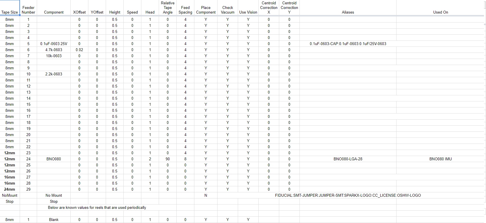
Let’s discuss each column and what it does:
Tape Size: Just for humans. It’s nice to know the size of each feeder so when I need to add a 8mm tape I can quickly see which 8mm slots might be open.
Feeder Number: The machine has the feeder locations hard coded. When it is told to pick from feeder number 6 it will go there and pick from the zero location unless the user adds an offset.
X/Y Offset: Usually zero if a component is normally shaped. If you have an oddly shaped thing like a connector and the weight is not evenly distributed you may not want to pick from the center of the pocket. Offsets allow you to adjust where to pick up the component at a given feeder.
Height: I’ve never changed this from 0.5mm. You may want to change the height for large components on designs that use thin (0.8mm) PCBs.
Speed: 0 means this component will be placed using the global pick speed (usually 100% speed). If you have a large component that requires extra precision you could set this to something lower like 70, meaning the machine would pick and place this specific component more slowly at 70% speed.
Head: We’ve loaded our machine with the two smallest heads: Juki 503 and 504. Head 1 is 503 and good for small components like 0603s, diodes, LEDs, etc. 504 is good for larger ICs such as QFNs, SOICs etc. So depending on the size of the component you’ll set the head to 1 or 2.
Relative Tape Angle: This is an important one! And a very handy one. When you create a footprint in EAGLE it may be in any orientation. But when the machine picks the component from the tape it may be different from how you made the footprint. This column tells the script to add or subtract an angle from the placement angle in your design. You’ll know you need an offset when the machine places your component 90 or 180 degrees off. Don’t worry, you can check the angle before you pick anything. Note: A 90 degree turn means the machine will pick the component from the tape and rotate counter clockwise 90 degrees.
Feed Spacing: This is the distance between components in your tape. Each time the machine picks a component it will advance the tape this number of millimeters. The industry is set to 4, 8, 12, 16mm. There is no tape with a 5.2mm spacing (that I have heard of).
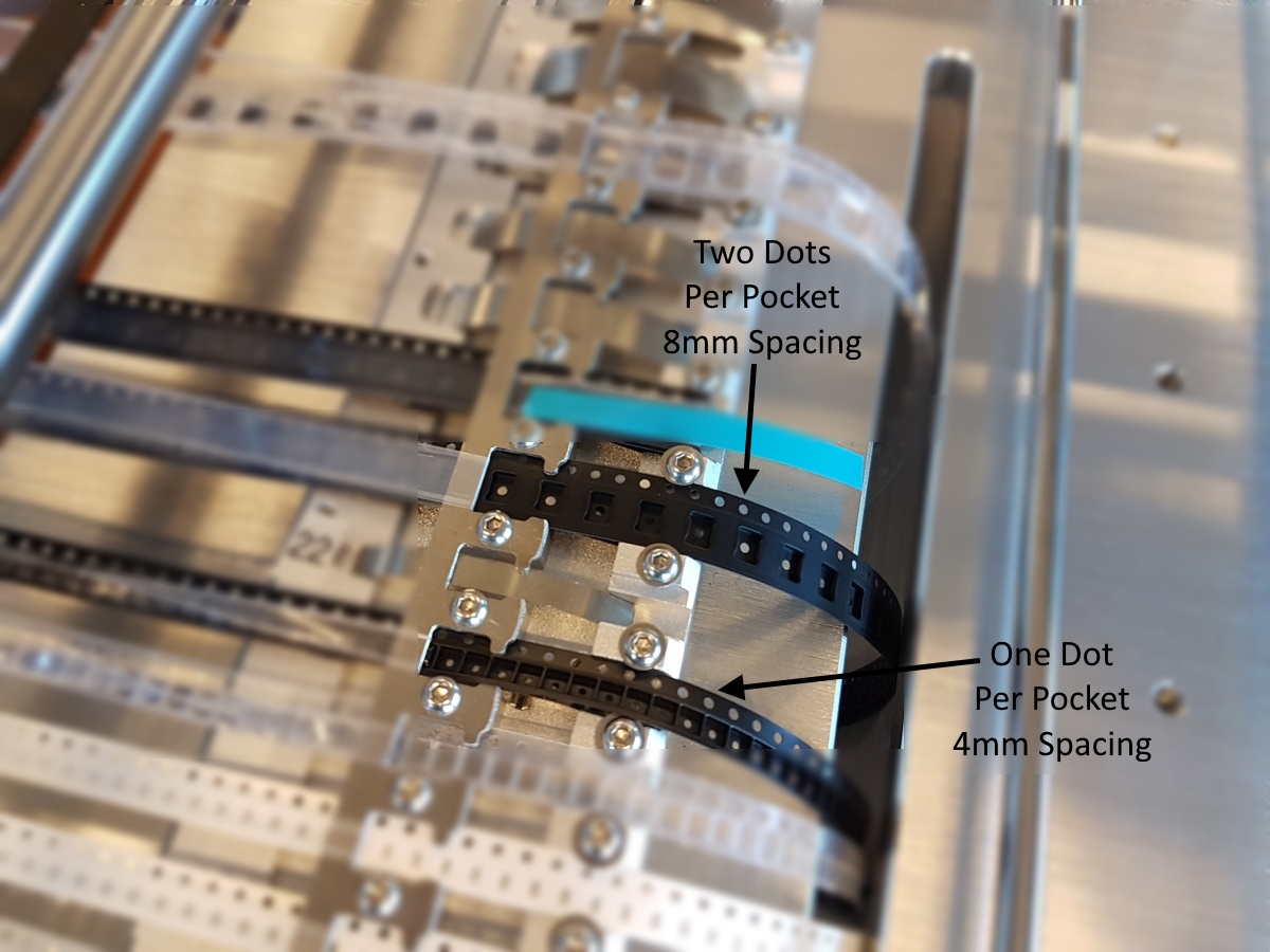
You can measure this with calipers or you can look at the holes at the top edge of the tape: if there is one hole per pocket that’s 4mm spacing, if there’s two holes that’s 8mm, etc.
Place Component / Check Vacuum / Use Vision: These are booleans to control whether you want to place the component, check the vacuum when placing this component, and use the vision system when placing this component.
- Place Component: There are various times when you don’t want to place a component. If the machine just can’t handle this particular package then you can set it to N and place the component by hand after the other 98% of the board is populated.
- Check Vacuum: The machine will pick the component and if it doesn’t see a change in vacuum pressure then it will assume if failed to pick the component and try again. I have not yet used it but let’s say you’ve got a weird connector that has a rough top surface. I could imagine you would get a false negative (the nozzle picked up the component correctly, it’s just losing lots of air while it’s doing it) so you can turn this check off for this component if you want.
- Use Vision: I have had a few instances where the vision system could not correctly identify the outline of the component. When this happens the machine will go and try to pick another component, often failing a second time, losing expensive components along the way. Turning off vision will force the machine to place this component but with less accuracy. Turning off vision for a component will also allow the machine to place them much faster. I will often turn off Use Vision for small 0603 resistors and caps knowing that the molten metal from the reflow process will correct any small inaccuracies with the placement.
Centroid Correction X/Y: This column is only used with our KiCad conversion script. KiCad uses the origin of the footprint you’ve created rather than finding the centroid of the component. This column lets us adjust known wrong part origins. For EAGLE users you can leave this as 0.
Aliases: This is a big one. I’ve seen all sorts of odd part names in Eagle. Sometimes it’s 0.1uF, sometimes it’s called CAP-0.1uF-0603. The alias column allows us to tell the script that if it sees a 0.1uF/25V-0603 it’s actually the 0.1uF-0603 cap sitting in feeder 5. Be careful! We’ve populated the wrong part because the wrong alias got listed for the wrong part. How to use the alias column: Run the ULP. If it says ‘Hey I don’t have a feeder for this part called myCap-0603-0.1uF’ then you know to go to feeder 5 and add an alias called myCap-0603-0.1uF. Re-run the ULP and the 0.1uF should be correctly added to the work file. Use colons “:” to separate items in the list (do not use commas!).
Used On: The ULP doesn’t look at this column, it’s for humans only. It is handy to know that the 27 Ohm resistor is used on the GPS breakout and the Pulse sensor. That way if I need to add a component to the machine I can quickly realize I don’t plan to build GPS or Pulse sensor for awhile so I can remove the 27 Ohm feeder and use its location. See the Stop tag as well.
No Mount: This is another important item. It’s grouped as a feeder but it’s not. When the script sees one of the items in the alias list it will not add the device to the work file. This is handy when you need to ignore components like silkscreen logos, fiducials, etc.
Stop: This is the tag to tell the script to ignore any following lines. We ‘store’ feeders down here when we’re not using them. For example, there’s only two 16mm feeders on the machine. If we need to remove a 16mm feeder and swap it out for a different 16mm feeder we will move that line of data down below Stop. That way we don’t have to re-type it or remember it, we can just move it back above Stop when we put the component back on the machine.
This may seem like a lot of work but it will save you loads of time! I promise.
What’s the Python Script for?
An EAGLE ULP can only look at local files. How do we get from this google spreadsheet to a local file? That’s what UpdateFeederData.py is for. This python script (it’s turtle scripts all the way down) will download the public google spreadsheet to a local CSV file. The ULP then loads this CSV to do its work. The python script will run each time you run the ULP so you shouldn’t need to worry about it. Why did I use a public google spreadsheet? Because I’m too lazy to correctly use OAUTH and JSON to authenticate with Google.
Workflow
The workflow looks like this:
- From the PCB we want to build, run the ULP and see what components can’t be identified.
- Add aliases to any common parts that you see.
- Re-run ULP and verify common parts are being added to work file.
- Mount any new components to the machine and add them to open Feeder Numbers in the spreadsheet. Fill out any settings for the component you may know inside the spreadsheet.
- Re-run the ULP and verify the new parts are being added to the work file.
- Start the machine software and load the work file.
- Verify (via the Run/Edit/Feeders menu) that the feeder information for the new component is correct. Any changes like tape advance, offset (rarely needed), head number that need to be made should be made in the spreadsheet. Then...
- Re-run the ULP and Re-Edit the work file verifying that the new component info is correct.
- Now check a new component in the Run/Edit/Components list. Inspect where it is being placed. Does the orientation make sense? Do you need to add a Relative Tape Angle to get the orientation correct? If yes, update your google spreadsheet, re-run the ULP and check again.
This may seem like a lot but you only have to do this once for each new component instead of every time you create a design. Using this ULP and spreadsheet we can get the machine placing components on a brand new design within a few minutes because 90% of the components on that board are known and have been used before.
Let’s Do It!
It’s important to me that this example runs for you so I’ve tried to include all the necessary files with lots of screenshots.
If you haven't yet please install the Charm High software.
Start by downloading the repo either via git or grab the zip. Unzip this into a directory that you can easily find with EAGLE. You will also need python 2.7 installed. If you don’t have python, that’s ok, you can skip it for now you just won’t be able to update the feeder information.
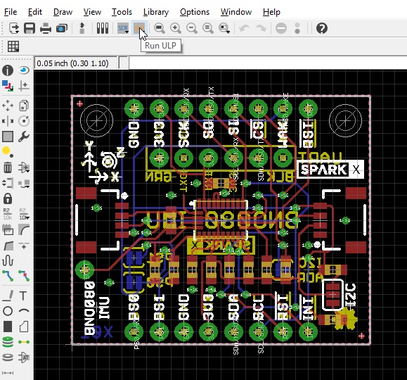
Open the BRD file in EAGLE. This is the design for our VR IMU using the BNO080. Click on the ‘Run ULP’ button.

Select the 'ConvertToCharm.ulp' file.
The ULP should then ask you where you want to save the *.dpv work file. For now, save this file in a directory you can easily get to. In the future, you’ll want to save it to the /[Charm High Software Directory]/Files directory so that you can open the work file from within the pick and place software.
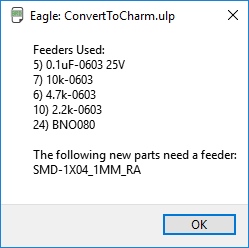
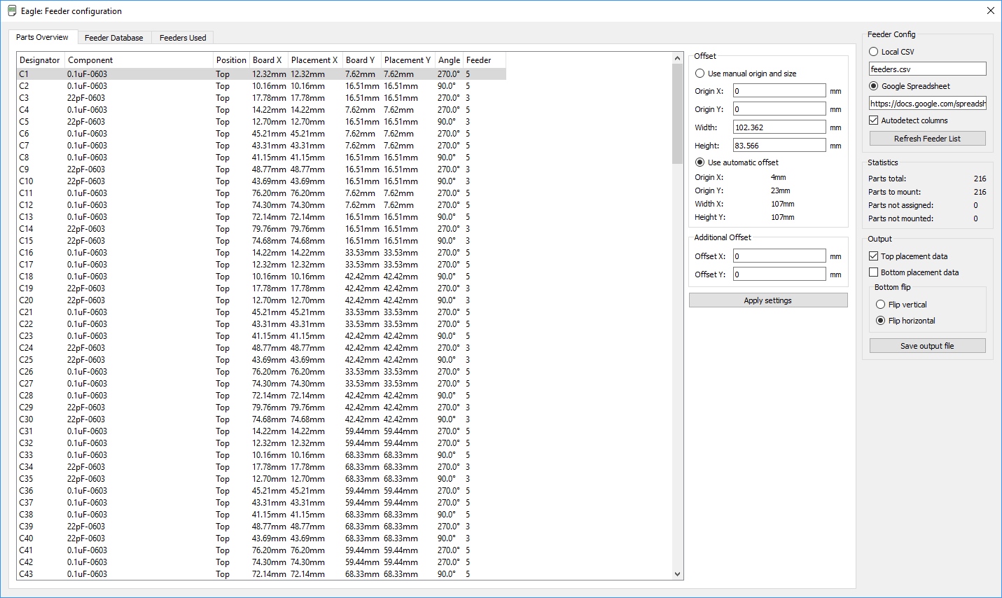
Upon completion the ULP will let you know which feeders it is going to use and which components, if any, it could not find in the feeder list. This is helpful when identifying obvious components that should have an alias in the feeder list. You should be able to quickly add an alias and re-run the ULP to correct those. This will also let you know of legitimate new components that you need to add to the machine and to the spreadsheet.
Now let’s open up the work file in a text editor:
It’s pretty easy to begin to see which parts of the file are responsible for which bits. But it makes much more sense if you open this work file in the Charm High pick and place software.
We’ll have a tutorial setting up and using the software soon. For now you can get the software from our repo. Please run the executable and wade through the non-english prompts as best you can.
Please re-run the ULP. This time save the *.dpv file to the work files directory. If you installed the software to the default location this will be
C:\CHJD_SMT\Files
Now run the pick and place software from Charm High. You will get Serial errors and Unable To Zero errors - that’s all ok, you don’t have a machine after all!
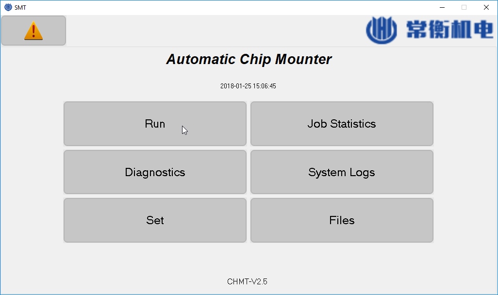
Once the software is started click on Run.
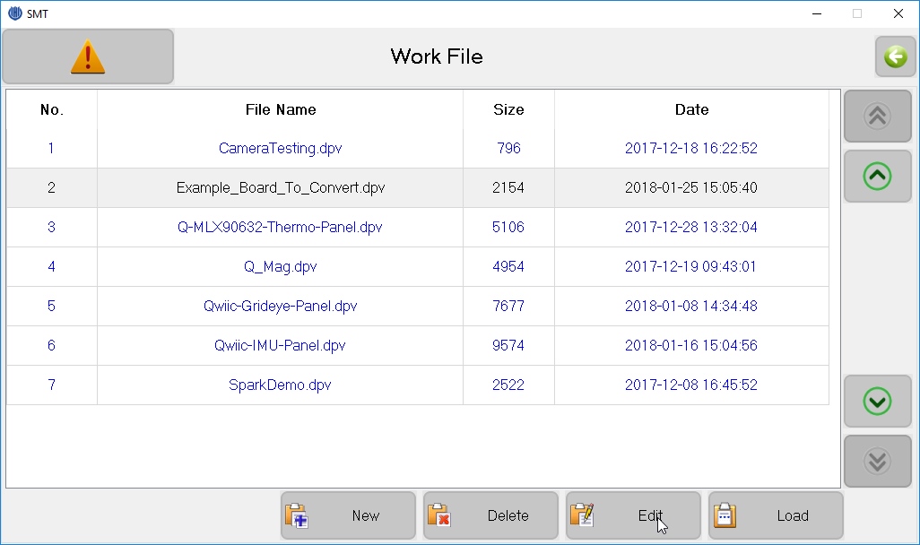
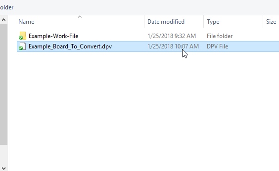
Select the Example_Board_To_Convert.dpv you created and stored in the Files directory. If you don’t see it, that’s ok you don’t need to shut down the software. Just hit the back button then use file explorer to move the Example_Board_To_Convert.dpv file to the correct \Files directory. Then click on Run again and the list will be refreshed.
Click Edit. You are now editing the work file you just created.
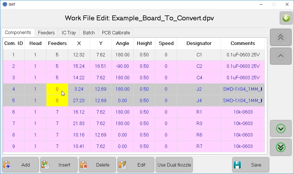
Note that lines highlighted in purple, gray and yellow. Purple means the component will be mounted and using vision. Grey means the component will not be mounted. And yellow means there’s an error. This component doesn’t have a feeder ID! Sure enough, this is the device that our ULP said it couldn’t identify so it couldn’t give it a feeder number. Click on the Feeders tab.
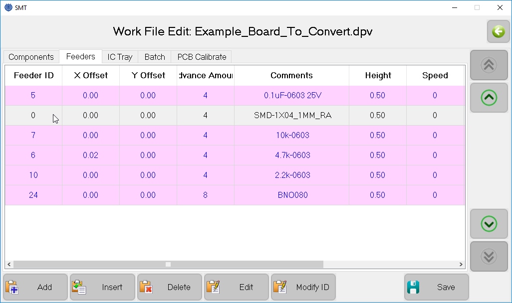
You’ll see SMD-1X04_1MM_RA is gray with no ID. Before you can start a job all feeders need an ID. You could Delete this feeder (it will then remove all related components) or you can Modify ID. If you want to mount this part using the machine you will need to add it to the spreadsheet, re-run the ULP, and then re-open the work file in the software.
I never Add or Insert a feeder - I work exclusively out of the spreadsheet and ULP. The reason being is that I will probably need to tweak lots of small things along the way and every time I re-run the ULP I would also have to re-delete this feeder, or re-tweak that one component location. It’s better to change a few globals than lots of locals.
What about other machines? What about KiCad?
We have created a KiCad to Charm conversion script in Python. We don’t have many designs in KiCad so the script is not nearly as developed as the Eagle ULP but it functions the same: pull in feeder data, compare with parts on the board, output a dpv file.
Wayne and Layne have done some excellent work creating a python script to convert KiCad for their machine (the TM-240A). The script is excellently written but I am unfortunately unable to get the script to run (my own python lack of knowledge). That said it looks like you have to set the feeders each time you run the script. If you’re doing lots of different designs I reiterate my opinion that you need a central point for your feeder data. It’s a big time sink to have to re-enter feeder info each time.
Dangerous Prototypes has a bit about the file format for their TM-240A. It may be of use for further deciphering the work file.
I Got a ‘Python script couldn’t run’ Error?
The first thing the SparkFun Charm Converter does is attempt to download the google spreadsheet in CSV using a python script. If it fails it will give you this error. This is probably happening because you don’t have python 2.7 installed and/or python is not in your path.
Whew!
Congrats! You made it through our ULP script! We hope you can get as much benefit from it as we do. If you have recommendations for changes please let us know on the issues tab. We welcome pull requests and help making the code cleaner.
Thanks for reading! Please checkout the other posts on our desktop pick and place machine.
Do you have one of these machines? Want to share your tips and tricks and ask other owners a question? Join the Desktop Pick and Place google group!
Related Pick and Place Blog Posts:
- Unboxing the $2800 desktop pick and place machine
- Creating a Leader for Cut Tape Components
- Installing the Charm High Software
- A better English Translation for the Charm High Software
- An EAGLE ULP script to create a CHMT36VA work file and start placing components in less than a minute!


