Making a Weather Station at SparkFun HQ

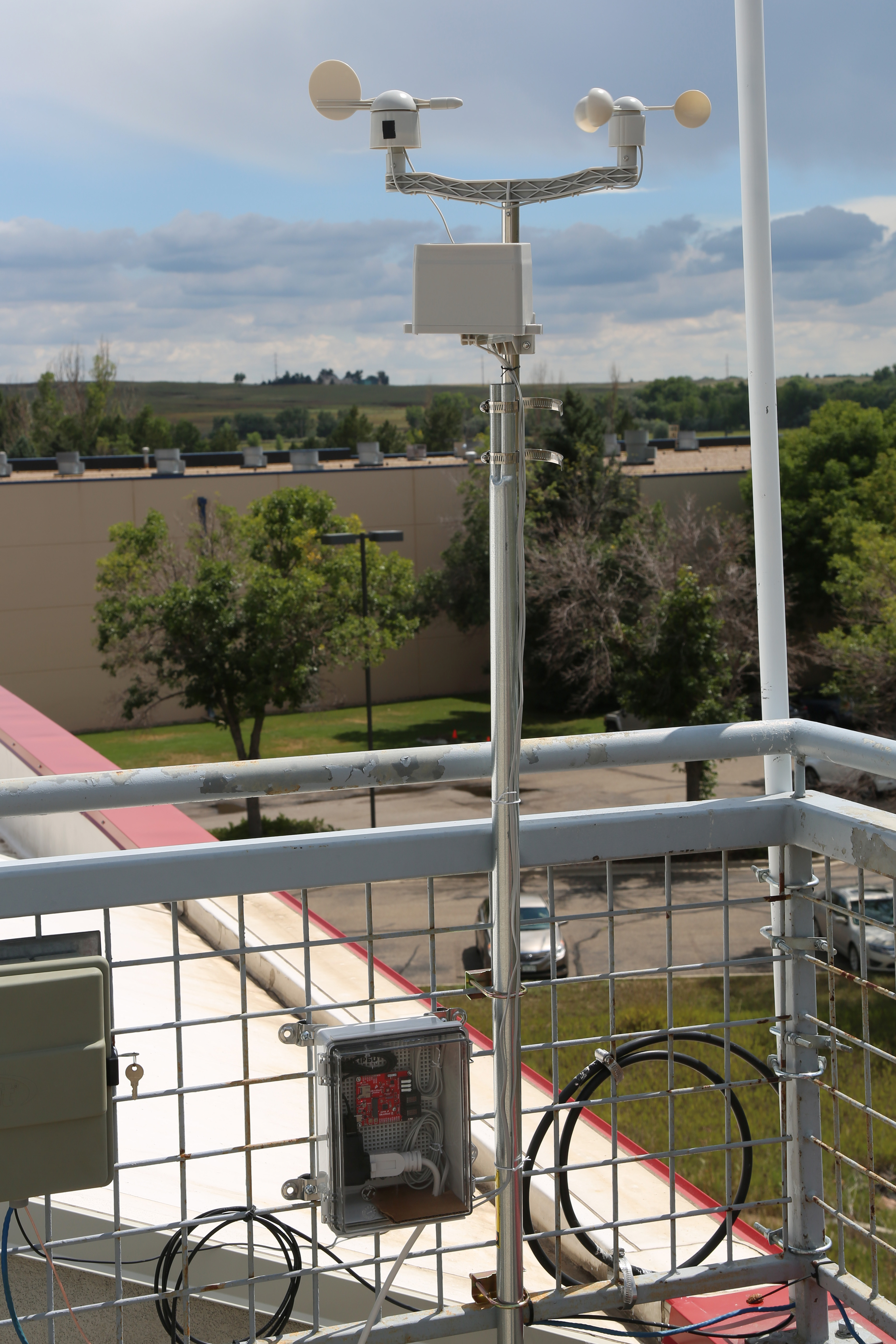
Check out our latest project! We mounted our SparkFun Arduino IoT Weather Station to the roof at SparkFun HQ.

Favorited Favorite 2

Have you ever wanted to create your own IoT weather station? This project demonstrates how to create a weather station monitored with Arduino Cloud.

Project Considerations

Before proceeding with this project, there are many considerations to factor into your design choices. The following are a few examples, but not the extent of the factors that may affect your weather station.

  • Soil Moisture
    • In this project, we will not be incorporating the soil moisture sensor because our weather station will be mounted to the roof of the building. However, users will need to account for the amount of cable required for their setup and the exposure of the electrical components on the sensor.
  • Humidity
    • While it would be ideal to house the electronics in a completely waterproof enclosure, this will greatly affect the readings from the sensors. With proper airflow, the humidity sensor will provide correct readings.
  • UV Light
    • The enclosure should allow UV light to pass through; otherwise, the UV sensor will not be able to make measurements of the sunlight. In addition, users should consider how the light will hit the sensor throughout the day.
  • Temperature
    • Similar to how a greenhouse traps the Sun's energy inside to keep plants warm, an enclosure can also be susceptible to the greenhouse effect. In this case, the inside of the enclosure would heat up beyond the ambient air temperature and provide inaccurate readings.
  • Environmental Factors
    • Weather and electronics usually don't mix well with each other.
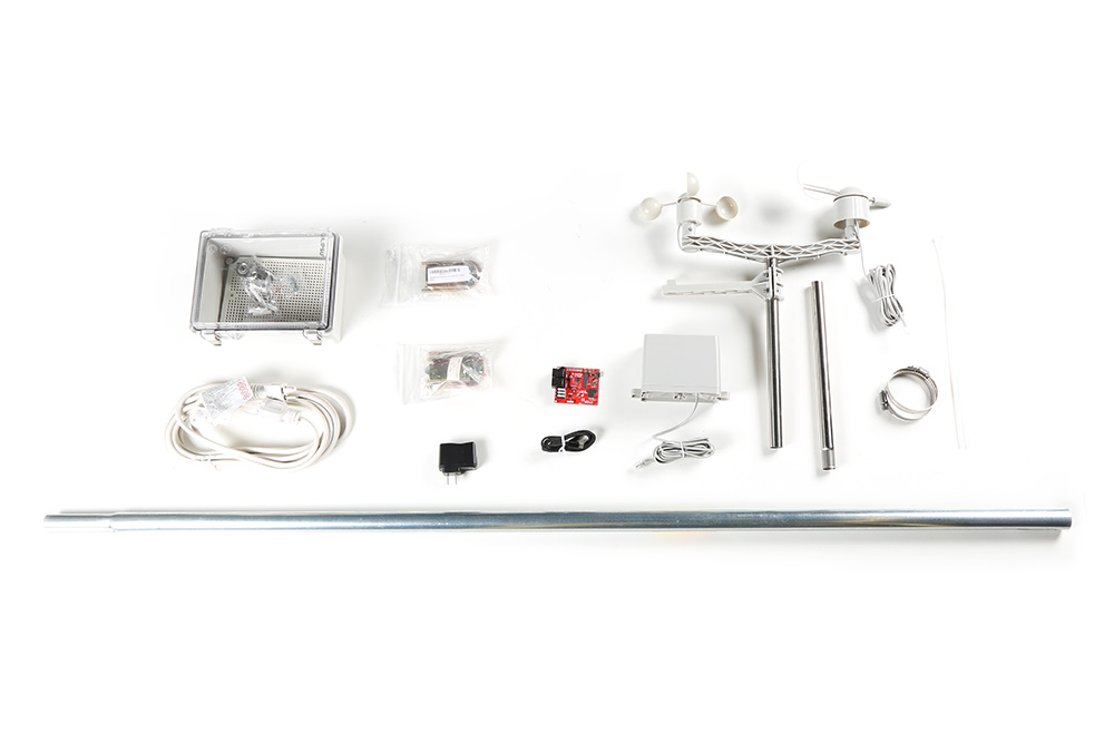
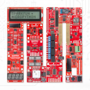
      • Dust and water are a recipe for disaster when it comes to electronics. You may want to consider a conformal coating to protect the board from the elements if you are not using a sealed enclosure.
    • When mounting your weather station outside, consider elements such as high wind, lightning, etc.
      • The pole in the weather meter kit is metal and could act as a lightning rod, where a lightning strike could arc and follow the power cable from the weather station.
      • With high winds, your innocent weather station may become a weapon of destruction if it gets loose.
      • For enclosures that aren't completely sealed, the combination of high wind and rain could allow water to penetrate the enclosure.
      • Even if your enclosure is completely sealed, you may want to have a desiccant bag to prevent condensation from forming. (As the enclosure is already sealed, the humidity readings will not be relevant.)

Materials

When it comes to measuring weather accurately, some specialized sensors are required. Luckily, the SparkFun Arduino IoT Weather Station includes almost everything required to build your weather monitor station.

  • Users will need to purchase a compatible enclosure, mounting hardware, and power accessories separately. (Most of these items can be found at your local hardware store.)

Materials for project
Parts used in our weather station setup. (Click to enlarge)

Hardware Setup

Weather Meter Kit

Users will need to assemble the weather meter kit. If you are unfamiliar with the weather meter kit, check out our assembly guide:

Weather Meter Hookup Guide
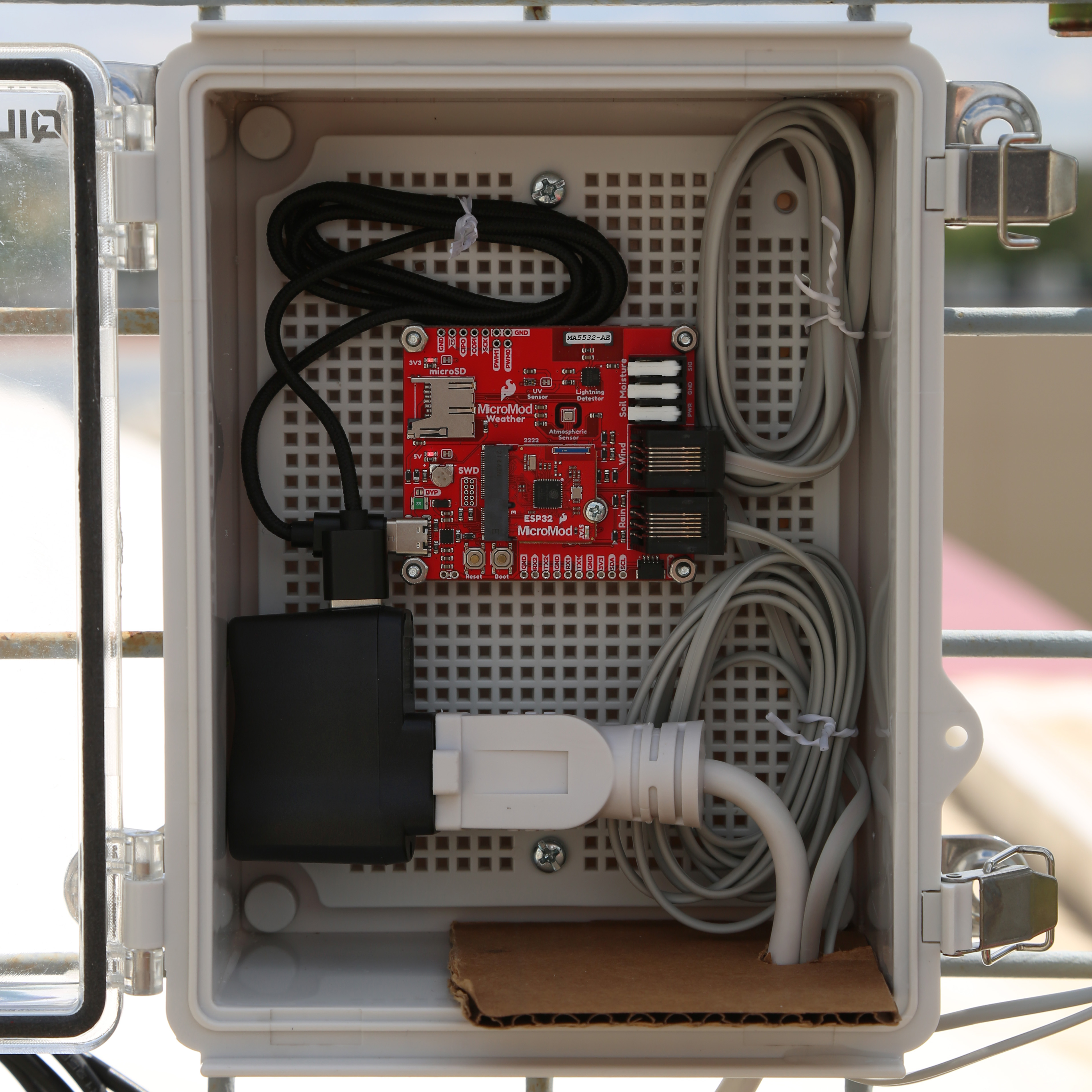
July 20, 2017

How to assemble your very own weather meter!

Enclosure

The enclosure houses the electronics and protect them from the elements. We recommend that users avoid utilizing a metal enclosure; the metal can potentially cause interference in the WiFi signal to the ESP32 microcontroller.

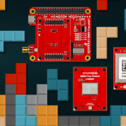
  • Attach the MicroMod ESP32 Processor board to the Weather Carrier board.
    • Program the board (see Software Instructions section below)
      Note: We recommend that users program their board and test their sensors and WiFi connection in a controlled setting before mounting any outside hardware. This will facilitate troubleshooting and isolate issues related to the enclosure, mounting hardware, mounting location, and/or WiFi connection.
  • Mount carrier board to the enclosure
  • Drill hole(s) for wiring

Parts in enclosure
The electronics housed in our enclosure. (Click to enlarge)

Note: If you are unfamiliar with our MicroMod products, please check out the following hookup guides before proceeding:

MicroMod ESP32 Processor Board Hookup Guide

October 21, 2020

A short hookup guide to get started with the SparkFun MicroMod ESP32 Processor Board.

MicroMod Weather Carrier Board Hookup Guide

January 14, 2021

A quick guide to help to create your own MicroMod weather station using the MicroMod Weather Carrier Board and Processor of your choice.

Mounting the Weather Station

  • Mount the weather meter kit
    Note: When mounting the weather meter kit, orient the wind vane sensor to the appropriate cardinal directions. Otherwise, users should recalibrate the sensor's ADC values in the Arduino sketch.
  • Mount the enclosure
  • Connect the power and RJ45 sensor cables to the weather carrier board

Weather station on roof
Our weather station is mounted on the roof of the SparkFun HQ building. (Click to enlarge)

Software Instructions

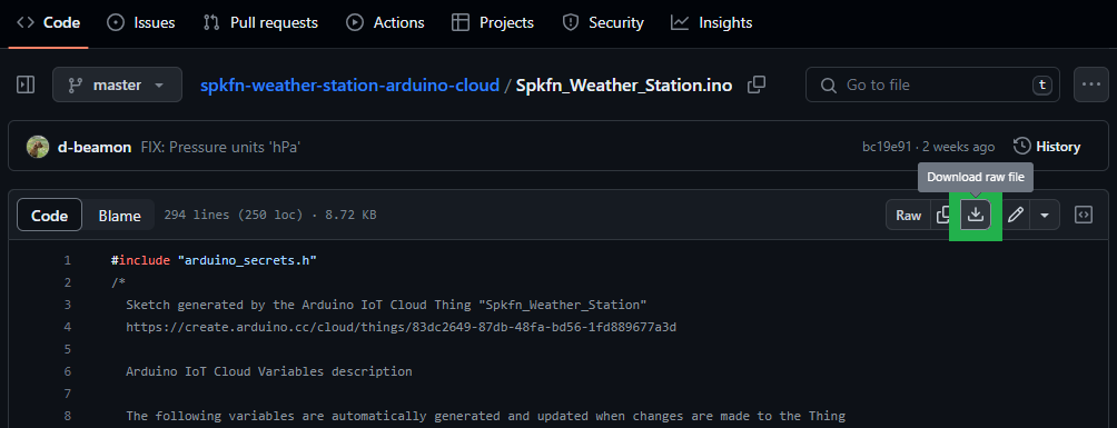
The software and project instructions can be found on the Arduino Project Hub: Weather Station with Arduino Cloud. Users can also download the code from the GitHub repository for the project.

Download button
Click on the button (green) to manually download the Arduino sketch. (Click to enlarge)

Note: The Arduino Project Hub post does a great job of summarizing the information needed to set up your device and dashboard. However, if you are still familiar with the Arduino Cloud platform and would like to see their full instructions on creating a device, configuring a thing, and dashboard, please check out their getting started tutorial.

Getting Started with Arduino Cloud

August 30, 2023

Arduino Cloud is the next exciting journey to bring your creations to life in a snap. It’s an all-in-one IoT solution that empowers makers to create from anywhere, control and share their projects with stunning dashboards..

Note: In the Project Hub post, there is a table of variables from the Arduino sketch. The Starting Plan column indicates which Arduino Cloud plan(s) will allow users to access those variables (see the Note below).

thing variables
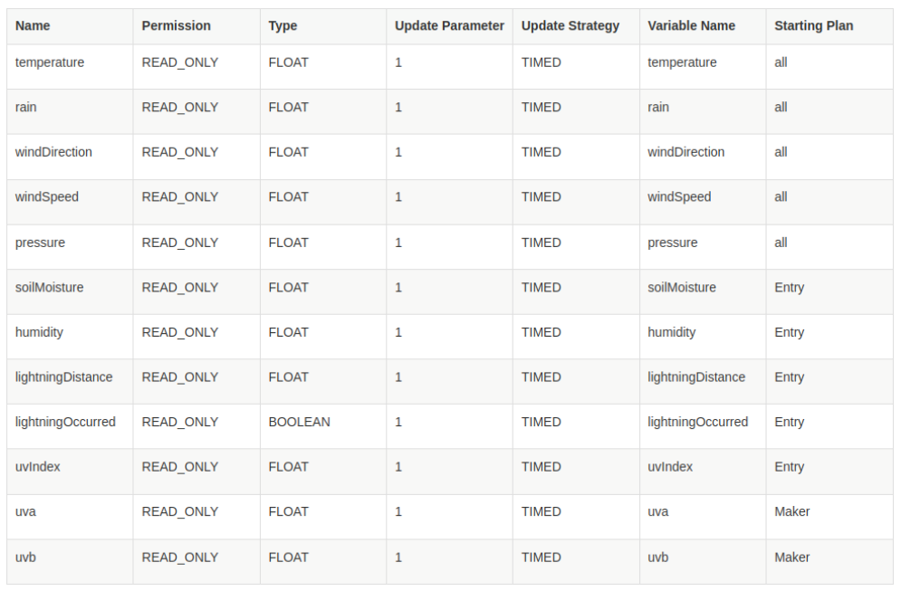
Arduino Cloud plans and the variables available in the Arduino sketch. (Click to enlarge)

Note: Depending on your Arduino Cloud subscription, you have a limit on the number of maximum variables that are available to configure. (Check the full list of supported features for each plan.)

Maximum number of variables per plan:

  • Free: 5
  • Entry: 10
  • Maker and Maker+: Unlimited

For example, you only have to create _uvIndex_ variable if you have an Entry or superior plan ( Entry, Maker, or Maker +).

Enjoy!!!

After the hardware setup and programming was done, we set up our Arduino Cloud account and created our dashboard. The new weather station was then mounted on the roof of the SparkFun HQ building. Here is a look at the data from our new weather station on the Arduino Cloud dashboard:

Arduino Cloud dashboard
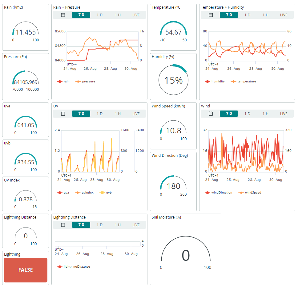
A screenshot of the dashboard on the Arduino Cloud platform displaying the data from our weather station. (Click to enlarge)
historical datal
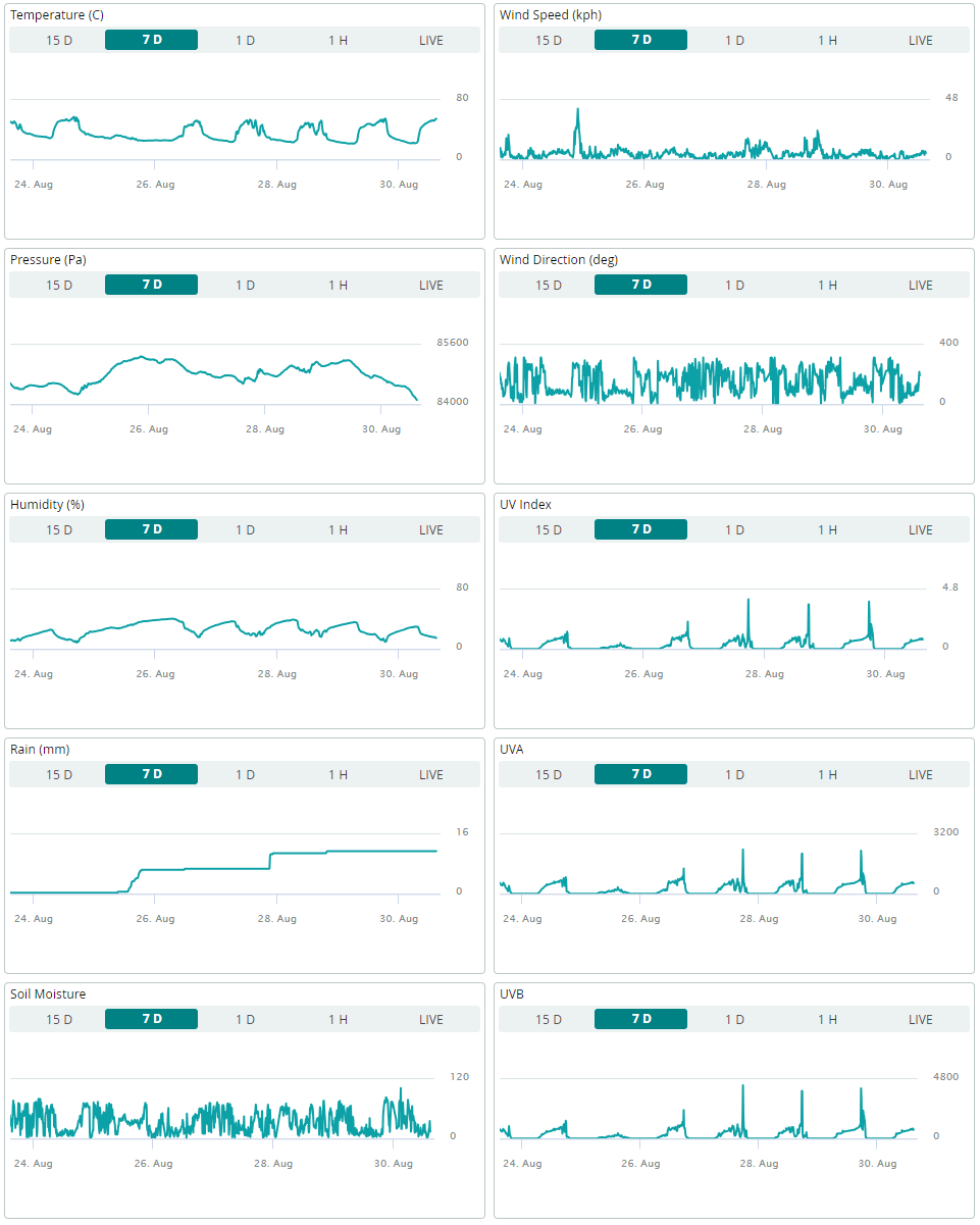
We also created a separate dashboard to display historical data from the last week (previous 7 days). (Click to enlarge)

Note: Currently, you cannot publicly share a live view of your dashboard. However, the Arduino Cloud platform does allow users to share their dashboard directly to other users (via email link).

Are you ready to connect your IoT Weather Station to Arduino Cloud?


Comments 10 comments

  • Member #760092 / about 5 months ago / 1

    Just getting started on the assy and hookup of my weather station. I like the enclosure you selected, but would like the humidity and temp readings to be accurate. Have you considered venting the enclosure? If so, what about vents on the bottom to allow airflow into the enclosure? Any experience with venting an outdoor box to be relatively rain proof like a U shaped upside down pipe on the top for instance? Probably need to add a screen or filter to keep the bugs out. Also, if I add a desicant bag to keep moisture pout, it seems it might mess up the humidity readings? Thanks for any help you can suggest. Long time SparkFun fan.

    • santaimpersonator / about 5 months ago / 1

      You could ventilate the enclosure; however, that would expose all the electronics to the elements. Instead, I would recommend utilizing a Qwiic cable to include the Qwiic Atmospheric Sensor outside the enclosure. That way, at worst, you only lose a $16 sensor and not all the electronics. You can also add a conformal coating to the sensor board to increase its durability; just don't coat the sensor.

      Note: This modification assumes you understand the required code changes for the project.

  • Member #714284 / about 8 months ago / 1

    I completed a similar project years ago with my son. We used a Sparkfun tutorial that detailed how to build a weather station with Sparkfun components/parts.

    In this post, you mention temperature and humidity under the 'Project Considerations' section. However, it appears the dashboards are showing temperature and humidity even though the board is enclosed. How did you get those to read correctly while enclosing the board? We ran into that problem years ago and never did figure out a great solution.

    • SparkFro / about 8 months ago / 1

      Hi there!

      We included the temperature and humidity measurements in the dashboard to show them off, but the exact values are not an accurate measurement of ambient conditions with this particular enclosure. Because of heating from the sun, the temperature usually gets in the range of 50C to 60C, despite the air temperature only being around 30C. So the exact values aren't accurate, but we can at least see the daily heating cycle, and even estimate how cloudy a day is from the relative temperature.

      Getting accurate values wasn't important for our quick demo here, but if that is important for you, then you'd need to choose your enclosure carefully to allow decent airflow without letting the electronics get rained on or anything. There are solutions for that, but that was beyond the scope of this demo.

      Hope this helps clarify!

    • Member #358569 / about 8 months ago / 1

      I bought the Ambient Weather temp/humidity shield and this worked very well to ensure that readings were accurate: https://ambientweather.com/amwesrpatean.html

      However, I didn't use any conformal coating, and I went through two weather shield boards in the span of 3 years. I think that conformal coating (with care not to cover any sensing apertures) plus the shield are the way to go. What would be really nice is if the sensors were on a daughter board attached by wires. The brains of the unit should be sealed and the sensors should have access to the elements.

  • Member #134773 / about 8 months ago / 1

    I have a couple of comments (BTW, I'm a retired Engineer, and hold an "Amateur Extra Class" Amateur Radio license, and also in the late 1970s earned a First Class Radiotelephone license -- now called a "General Class" Radiotelephone license).

    First, since this project is dependant upon WiFi, it's best to avoid metal enclosures which can block the radio signals.

    Second, although your pictures show what appears to be a 120 VAC extension cord with a "wall wart" USB charger plugged into it in the enclosure, I'd be much more comfortable with keeping the wall wart and 120 VAC indoors, and just running a 5 VDC line out to the enclosure, even though it might mean a little bit of soldering to connect the 5 VDC line to the board, as long USB cables with a USB-C on the end are VERY hard to find. (Which brings me to another point: I just noticed that it would be a LOT more convenient if there were PTH connections for 5 VDC input on the carrier board.) As well as being substantially safer, getting the wall wart out of the enclosure means less heating being generated inside the enclosure -- making the temperature readings more accurate.

    • santaimpersonator / about 8 months ago / 1

      As mentioned in the note, we didn't list all the considerations for this project. Unfortunately, due to the nature of the project, this blog post wasn't intended to be a step-by-step tutorial listing out every technical aspect that users should consider; as each installation will be unique for each person. This post is just a short project write up for customers to reference; our primary highlight is the capability to turn this kit into an IoT device on Arduino's Cloud platform.

      • You do have a good point, some users may not consider the implications of utilizing a metal enclosures. I'll update the post to include some information about that.
      • Regarding power options, that will be up to the user to decide what works best for them.
        • There is a 3.3V PTH pin to power the board.
        • In our situatuon, we had access to a covered electrical receptacle on the roof's exterior. This fact, amongst other reasons, we chose to use an extension cable for our project.
          • Unlike our extension cord, the sheathing on most USB cables aren't rated for outdoor use.
          • A wall wart wouldn't be able to fit in the electrical socket cover.
          • We aren't worried about accurate temperature readings. Our enclosure doesn't have ventilation, so it basically turns into an oven due to the greenhouse effect.

      • Member #134773 / about 8 months ago / 2

        Yes, I understand that it isn't a tutorial, though a lot of people reading it are relatively new to electronics, and may not be aware of some of the issues.

        Thanks for pointing out that most USB cables aren't rated for outdoor use.

        As for connecting to the 3.3 V PTH pin, if the "run" to the power supply is more than a few feet, it's better to go into a 5V connection so that the regulator on the board can assist in making sure that the rest of the board can see "clean" power. In trying to come up with a "no-solder" way of doing this, I have yet to find a "USB-C plug to screw terminal adapter", but our friends over at Adafruit have a 2.1mm 5VDC Barrel Jack to USB C Adapter. I know I've seen "2.1mm Barrel plug to screw terminal" adapters, but don't have time at the moment to track one down, but you could "jury rig" with Adafruit's 2.1mm DC Barrel Plug to Alligator Clips and maybe some electrical tape (possibly the self-sealing stuff). Also I might point out that 3.3V DC wall warts aren't nearly as common as the 5V DC ones.

        As for the issue of the wall wart not being able to fit into the socket cover, I'm also pretty sure that I've seen "oversized" socket covers, though since SparkFun's facility is a commercial residence, it would require a licensed electrician to change it out, though changing the cover could be a "DIY" for homeowners.

        • santaimpersonator / about 8 months ago / 1

          I filed an issue in the GitHub repository for the weather carrier board. If/when we revise the board, the engineering team should see the request for a V_USB/V_IN pin to be broken out.

          • Member #134773 / about 8 months ago / 2

            Thanks!

            I meant to mention this earlier, but I've used "FFC" (Flexible Printed Circuit -- there are actually several names) to pass signals through "operating" windows and the seals on a fridge. SparkFun carries 2 and 3 conductor crimp-on FCI connectors (these are female, search on "FCI" for the maile connectors), but not the cable. I use the 4 conductor stuff and get both it and the connectors from DigiKey -- search for PSR1635 for the cable, and 65801-004LF to find 4 conductor connectors. They work well for I2C sensors.

Related Posts

Open-Source HVAC?

Recent Posts

Tags


All Tags