T³: Making Things Move with the Edison

Let's dissect another section of EdiBot 2.0 and learn how to spin DC motors with Python.
The Intel® Edison offers a few interfaces for working with hardware peripherals, and we have four Pulse Width Modulation (PWM) pins at our disposal. However, the PWM functions are fairly limited when compared with microcontrollers. For example, the I/O voltage is 1.8V, and you can only select a frequency between 4.6Hz and 4.688kHz in discrete steps (see Section 4.8 of the Edison Hardware Guide for more information).
That being said, the PWM, with some amplification, is enough to drive some gearmotors for a simple robot.
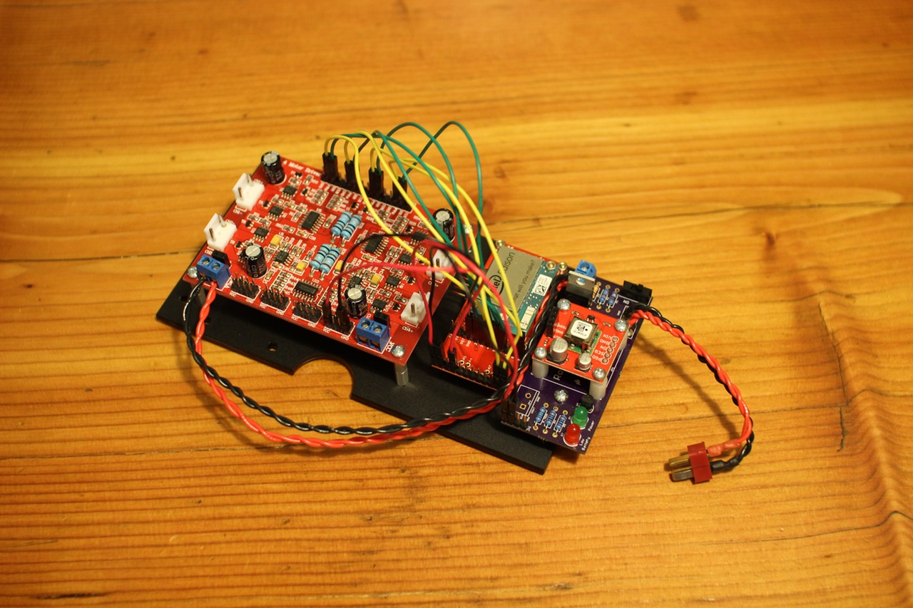
On the original EdiBot, I had trouble driving the four gearmotors on the Rover 5 chassis from just the Edison, so I took the long way around: Edison sends UART commands to an Arduino running Firmata, which then sends out the necessary PWM and DC voltage signals to the now-retired Rover 5 Driver Board.
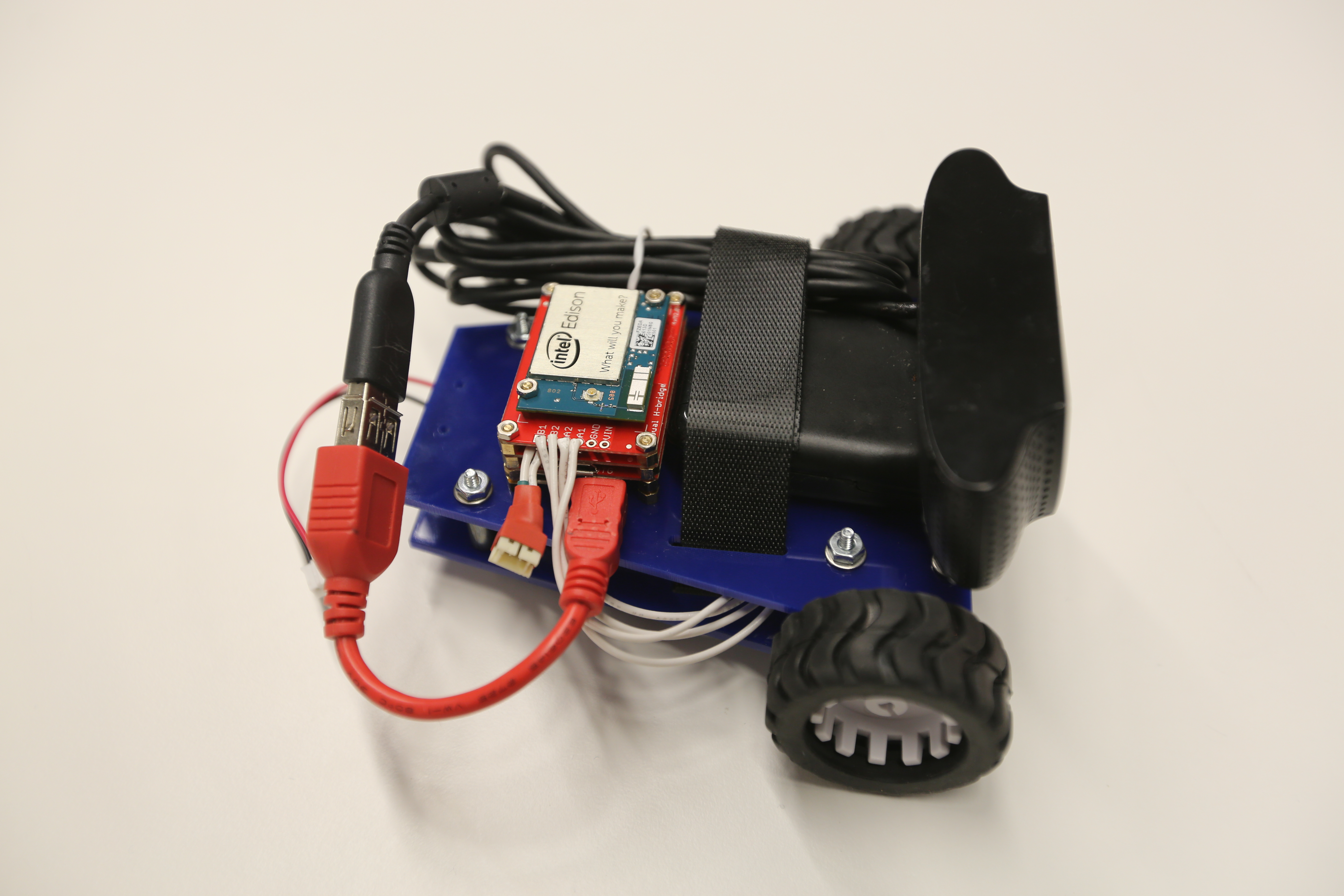
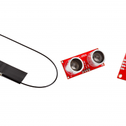
To control the motors on the revised EdiBot 2.0, I used:
- Edison Dual H-Bridge Block
- 2x 270RPM Micro Gearmotors
- 2x Micro Gearmotor Enclosures
- A pair of 42x19mm Wheels
- Some stranded wire
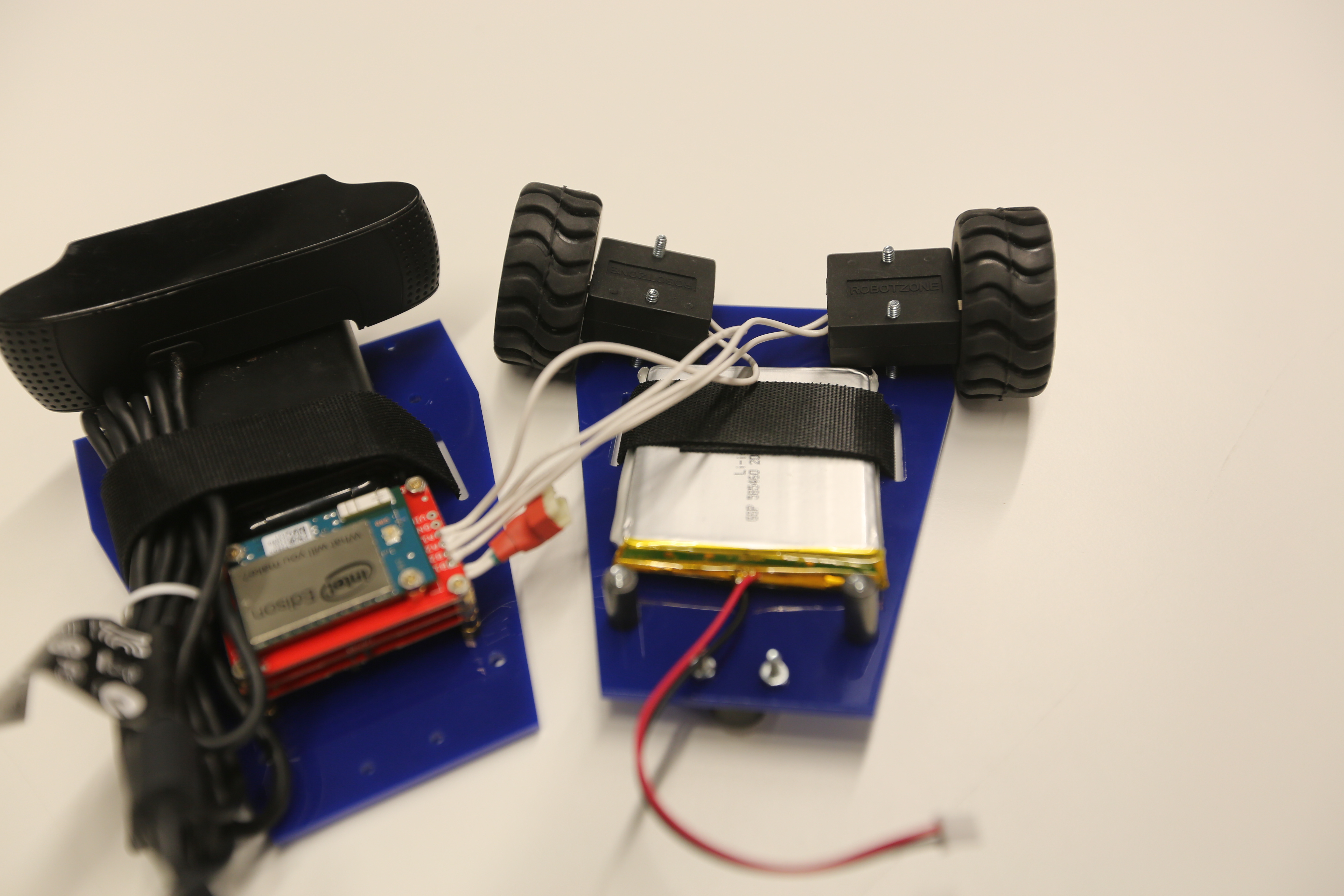
Even though the micro gearmotors are rated for 6--12V, we can get them spinning with a measly 4.2V (from the Edison's Vsys), and they have enough torque to move a little bit of weight (say, a lightweight acrylic chassis and some electronics). I also wasn't worried about drawing too much current, as the TPS62065 on the Edison Base Block could provide up to 2A, and the stall current on each of the motors was listed as 360mA (at 6V).
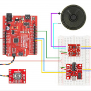
By connecting the motors to the A1, A2, B1 and B2 pins on the H-Bridge Block and soldering the "VSYS->VIN" jumper closed, we could construct a basic differential drive for the robot.

All we need to do is put a caster on the back of the chassis and we're good to go – now driving the motors at different speeds causes the whole robot to turn. One thing to note, however, is that the low voltage being supplied to the motors means that we really can't supply any less than about 50 percent PWM.
Upload the following Python code to the Edison to try out the differential drive:
import time
import mraa

# False: A is right, True: A is left
swapMotors = True

# Motor parameters. Set to 1 or -1 to change default direction
leftDir = 1
rightDir = 1

# PWM A (pin 12) is on pin 20 in MRAA
pwmA = mraa.Pwm(20)
pwmA.period_us(1000)
pwmA.enable(True)

# PWM B (pin 13) is on pin 14 in MRAA
pwmB = mraa.Pwm(14)
pwmB.period_us(1000)
pwmB.enable(True)

# Direction pins A1 and A2 are on GPIO 48 and 47 (33 and 46 in MRAA)
a1 = mraa.Gpio(33)
a1.dir(mraa.DIR_OUT)
a1.write(1)
a2 = mraa.Gpio(46)
a2.dir(mraa.DIR_OUT)
a2.write(1)

# Direction pins B1 and B2 are on GPIO 15 and 14 (48 and 36 in MRAA)
b1 = mraa.Gpio(48)
b1.dir(mraa.DIR_OUT)
b1.write(1)
b2 = mraa.Gpio(36)
b2.dir(mraa.DIR_OUT)
b2.write(1)

# Assign left and right motors
if swapMotors:
    leftPwm = pwmB
    left1 = b1
    left2 = b2
    rightPwm = pwmA
    right1 = a1
    right2 = a2
else:
    leftPwm = pwmA
    left1 = a1
    left2 = a2
    rightPwm = pwmB
    right1 = b1
    right2 = b2

# Standby pin is GPIO 49 (47 in MRAA)
standby = mraa.Gpio(47)
standby.dir(mraa.DIR_OUT)
standby.write(1)

# Differential drive. A and B can be -1 to 1.
def diffDrive(leftSpeed, rightSpeed):

    # Make sure the speeds are within the bounds
    if leftSpeed < -1.0:
        leftSpeed = -1.0
    if leftSpeed > 1.0:
        leftSpeed = 1.0
    if rightSpeed < -1.0:
        rightSpeed = -1.0
    if rightSpeed > 1.0:
        rightSpeed = 1.0

    # Set motor speeds
    leftSpeed = leftDir * leftSpeed
    rightSpeed = rightDir * rightSpeed
    if leftSpeed < 0:
        left1.write(0)
        left2.write(1)
        leftPwm.write(abs(leftSpeed))
    else:
        left1.write(1)
        left2.write(0)
        leftPwm.write(leftSpeed)
    if rightSpeed < 0:
        right1.write(0)
        right2.write(1)
        rightPwm.write(abs(rightSpeed))
    else:
        right1.write(1)
        right2.write(0)
        rightPwm.write(rightSpeed)

# Test the differential drive
diffDrive(0.8, 0.8)
time.sleep(1)
diffDrive(1.0, 0.6)
time.sleep(1)
diffDrive(-1.0, 1.0)
time.sleep(1)
diffDrive(-0.7, -0.7)
time.sleep(1)
diffDrive(0.0, 0.0)
That code should cause the robot to do a little dance: move forward, turn one way, spin another, back up, and stop. This differential drive code was used as the basis for EdiBot 2.0. The robot can locate a yellow object in its field of view, drive to face it, and back up if the yellow object takes up too much of the frame.
Want to make your own EdiBot 2.0? A full step-by-step tutorial can be found here.
