Enginursday: A Bigger & Better Mixer

-or- How I spent my winter vacation.
The typical SparkFun product is relatively small. When we design a breakout board, we're making a building block that will be incorporated into bigger projects. The building blocks themselves aren't particularly large or complicated: an IC and a few passive components on a PCB the size of a postage stamp.
Sometimes it's nice to work on something larger. I explored a much bigger design at the end of 2016, and I've finally got working hardware to show for it.
A Little Background
I play in a band. To be more specific, I'm a singing drummer...which in itself is a quandary. When I'm playing, I'm sitting inside a fairly loud musical instrument, and I still have to hear myself singing.
Long story short, on the advice of QCPETE, I gave in-ear monitors (IEMs) a shot, using his Tasty Blender headphone amplifier. After getting acclimated to them, I found that IEMs are great. I can hear myself singing, regardless of the room acoustics or available PA gear.
But it's added a bunch of gear that has to be transported, set up, operated and torn down...a mixer, microphone splitters, cables. To be able to provide two independent mixes for the IEMs, the mixer is bigger and more complicated than the task dictates.
I've played with mixer circuits for years (nearly every Forrest Mims book has a schematic for some sort of small mixer), and I decided it was time to actually make one into a rugged and complete finished device. So I decided to design a mixer that suits this application.
Design Targets
The ultimate goal is to spend less time setting up, and more time playing music. That breaks down into two concepts: simplicity and quality.
Simplicity
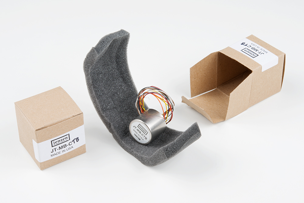
There are a couple of factors that can make things simpler. First, by incorporating the microphone splitters in the chassis, I can eliminate two pieces of equipment and the wiring they entailed, reducing setup time. For the splits, I selected Jensen JT-MB-C transformers.
Second, I eliminated extraneous features and controls. There are no controls that can accidentally disable the outputs. It's all analog, so there are no hidden modes or menus. A quick visual scan of the control panel tells the operator what's going on --- WYSIWYG!
Quality
Quality comes in a couple of forms.
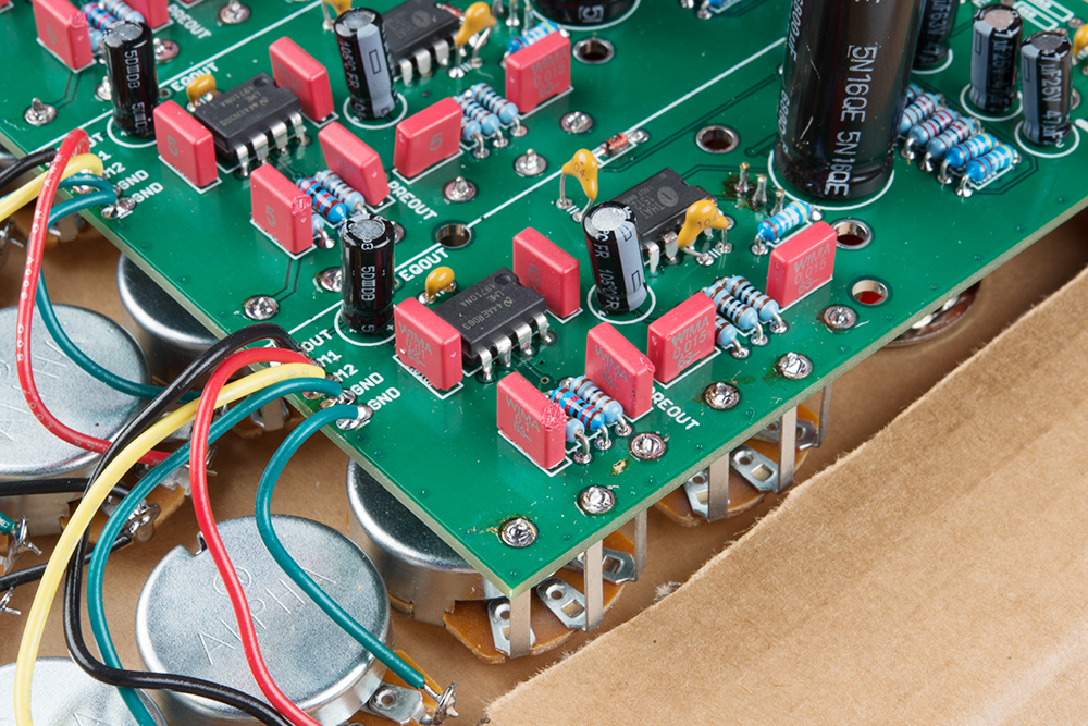
I started with trustworthy building blocks for the audio circuits: the preamps are THAT ICs, and the equalizers and summing networks are adapted from Doug Self's Small Signal Audio Design book. We'll cover these in more detail in a moment.
I also wanted to use high-quality components. The audio path uses 1 percent metal film resistors, Wima film caps, high-grade audio op-amps and low-ESR electrolytic capacitors. The connectors are all Neutrik. I even used shirt-button rectifiers, if for no better reason than I don't get to use them very often.
Ultimately, this mixer will go behind a metal panel that fastens in a Pelican case, with enough space to hold coiled cables alongside.
Basic Design

The basic design for the mixer is shown above. It consists of several basic building blocks.
Input Amplifiers
The four inputs are on Neutrik combo jacks, with a mic preamp on the XLR pins and a line input on the 1/4" portion. The input amplifiers are THAT 1512 ICs, the preamp cousin of the 1206 and 1646. The basic design for that stage comes right from the datasheet for the part.
I want you to tell me its name.
I'm telling you. It's THAT.
What's that?
This is THAT.
What?
THAT.
What's THAT?
IC.
What do you see?
THAT.
I see.
Yes.
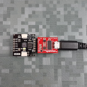
The line inputs are in parallel with the mic inputs, implemented as described in THAT design note 140. For the gain controls, I used the SparkFun Rotary Switch Pot breakout board, with resistors calculated for 10 steps of 6 dB each. The solid snap-action detent of the switch adds to the stage-worthiness of the mixer; they won't get bumped and knocked out of position.
Equalizer
Following each input amplifier is a simple two-band equalizer. For this, I used a Baxandall variant described in Doug Self's book. It's simple, and sufficient for the job at hand.
The EQ is buffered by an LME49710 op-amp, which feeds the channel's two send potentiometers.
The one possible drawback of the EQ stage is that it inverts the signal polarity...but we'll fix that in the next stage, bringing us to the...
Summing Amplifiers
The summing amplifiers are a simple unity-gain inverting op-amp summer, with AC output coupling also taken from Self.
There are no master level controls --- one fewer thing to have to adjust in the heat of the moment. Output levels are set by the send potentiometers.
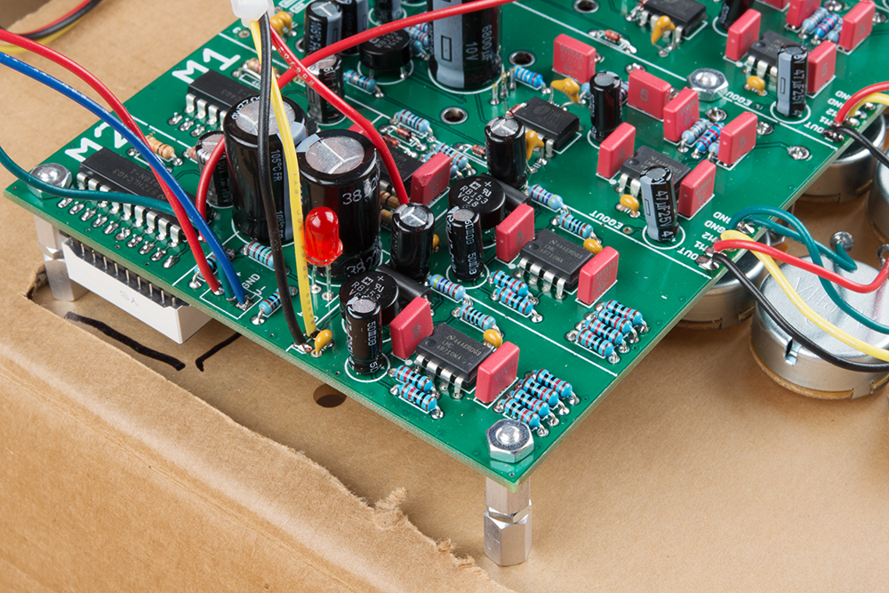
LED Metering
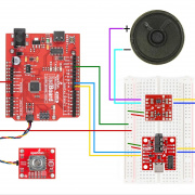
As an easy confirmation that the mixer was working, I wanted an LED meter on each output. The ol' National Semiconductor LM3916 VU-meter IC was a natural fit, along with some 10-LED bar graph assemblies.
Perusing the datasheet, I learned that I probably needed to condition the signal feeding the LED drivers. I added an op-amp to rectify and filter the signal, as described in Figure 19.
The PCB Layout
I took a few days' vacation at the end of the year, drinking hot cocoa, simulating circuits, and laying out a PCB. As I was beginning my design research, I got an email from Advanced Circuits in Aurora, Colorado. They have a PCB prototyping service at 33each.com, and they were removing their minimum order quantity. Where they had previously required a minimum order of 3 PCBs, I could now order a single board of up to 60 square inches for $33, plus shipping and handling.
That's a good enough offer for me to reconsider my approach. Rather than designing a small board, and using one board per input channel, I could put the whole mixer on a single, larger board.
But that leads to some other design challenges. A big board would require multiple copies of the same circuit, and managing them can be a hassle.
I opted to have a schematic sheet for each major section of the design. I did the schematic capture for the first channel, then copied and pasted it into the three following sheets. The same for the summing amplifiers and meters.
With everything copied and pasted, I ran the "renumber parts" tool in Eagle, and set it to increment by 100 for each sheet. When it was complete, I knew that C101, C201, C301 and C401 would be the equivalent capacitor on each input channel.
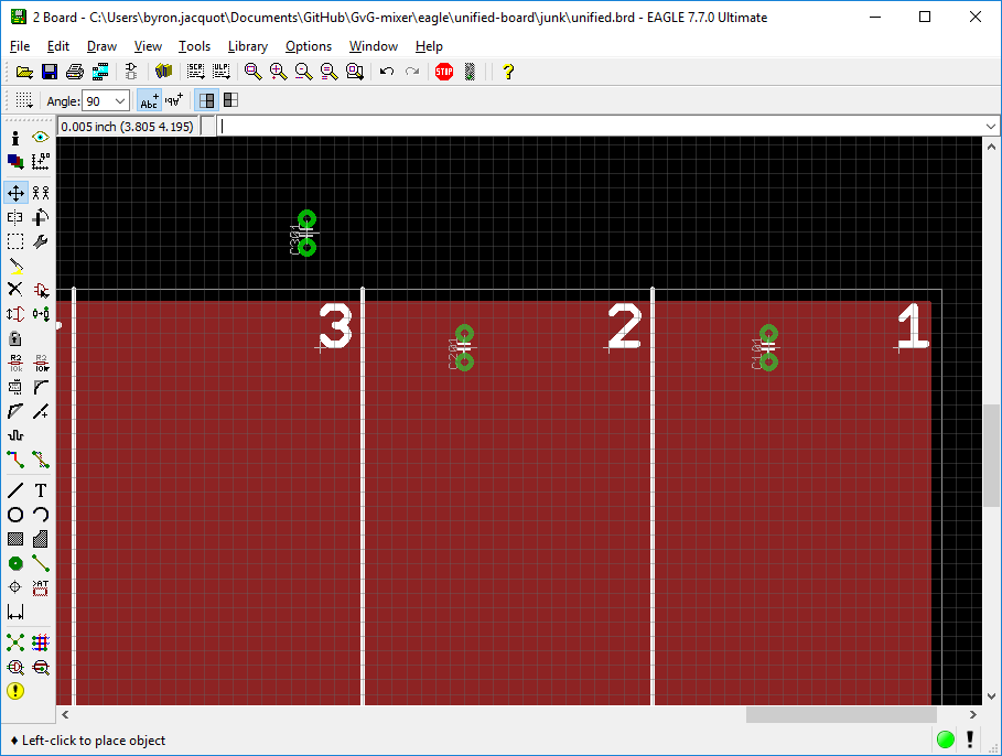
From there, I moved to board layout. I started by setting the board dimensions, and subdivided it into sections for each of the sheets in the schematic. Using the schematic as a reference, I moved the components for each section into place by typing their reference designators. Once the components were in place, I routed them similarly; I'd lay couple traces on one channel, then move over and lay matching ones on its peers.
Design Review
Before ordering the PCB, I ordered the components. When they arrived, I made a full-sized printout of the PCB art, and checked it against the actual components. I actually discovered a few small discrepancies between the footprints I'd used and the actual parts: the ferrite beads I received were about double the length their datasheet claimed!
I also had a couple of my colleagues look over my shoulder, making sure I hadn't missed anything silly. Again, some little fit & finish issues revealed themselves to fresh eyes.
If you're curious, you can find the files in my personal GitHub.
With that, I ordered the PCB!
Incremental Assembly and Bring-up
It's exciting to receive a PCB of this size, and very tempting to jump in and stuff all of the components. It can also be a recipe for a troubleshooting nightmare. If something isn't right, you might have to triage across multiple areas, and require rework multiple times.
So I worked more carefully, bringing up and testing each stage in isolation.
I built up the first input amplifier and tested it using a fixed gain resistor. Then I populated the resistors on one of the rotary switches, and added and tested the combination.
Following that, I built up the first EQ. By omitting the coupling capacitor between the preamp and EQ, I could inject external signals to validate its operation independently.
My methodical approach was rewarded by a relatively quick and simple bring-up process. The biggest stumbling blocks I encountered were flakiness caused by bad alligator clips, and not knowing how to get my signal generator out of frequency sweep mode (hint: the button labeled MOD is for MODe, not MODulation!).
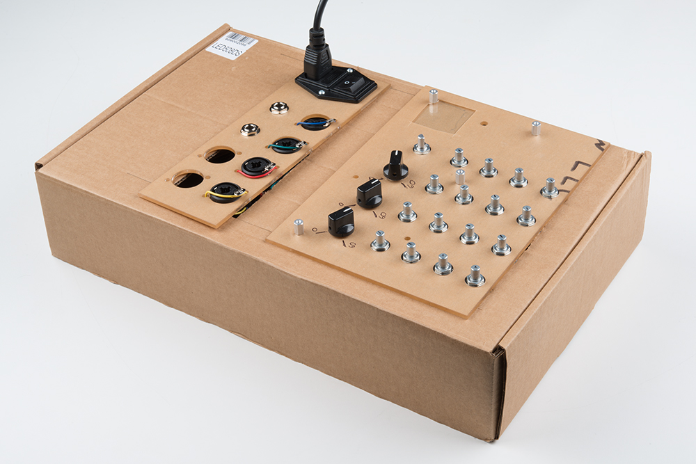
To make the whole thing strong enough to take to rehearsal, I laser cut some acrylic control panels, and cut a cardboard box to accommodate them. I also swapped the HP bench supply I'd been using to a Meanwell +/-15V supply.
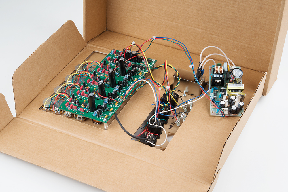
You'll notice two empty XLR knockouts in the connector panel. Those will be used for the split outputs in the ultimate version.
Initial Field Test
With everything behaving in the controlled environment of my workbench, it was time to graduate to testing in rehearsal.
Again, the basics work pretty well.
It took a little extra attention to get the gain staging set properly. It works better if the mix send controls are turned up, and the preamps are backed off. The opposite combination (high preamp gain followed by low bus send controls) tends toward clipping the preamps. When it's piped directly into your ears, clipping is obvious and distracting. The root cause is probably that the LED meters are a little insensitive, but they can be scaled using a single resistor.
It does sound good --- there is less background hiss than its predecessor, and it's easier to use.
Next Steps
With the electronics working, it's time to put them in an enclosure. The current plan is to remove the acrylic panels, and use them as templates to cut and drill some aluminum. Thankfully, the bass player is a metal fabricator, and I can hand that off to him!
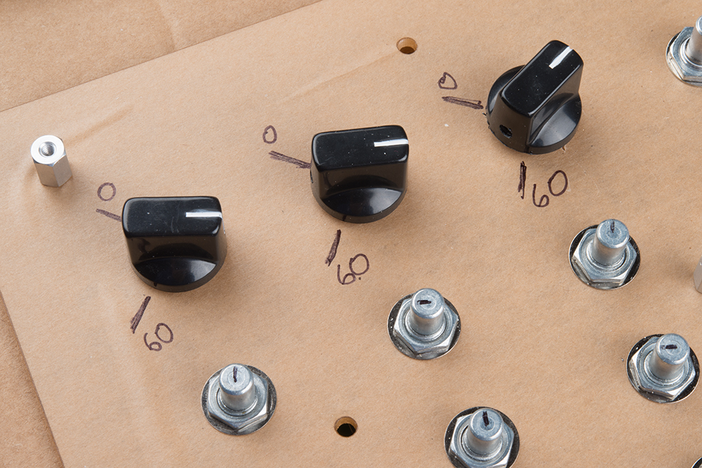
We'll also need to come up with some high-contrast markings for the controls, so that when the stage is lit by a single dim blue light, I can still tell what I'm doing. In the meantime, I'm getting by with Sharpie marks on the ends of the pot shafts.
Notes to Future Self
If I Have to Do It Again
I'm also living with a couple of small issues on the PCB. They don't impact overall performance, but could have been done better, anticipating how this prototype would be used. If I write them down here, I'll be more likely to remember them next time I'm making a board like this, and it might ultimately be the useful lesson you can take away from this article.
- First, there are test points nestled between tall components --- they're hard to hit with a scope probe.
- Second, some of the I/O connection pads have now seen a fair amount of rework, and are getting a little worn. I'm starting to worry about them lifting. Moving them to a larger pitch connector with bigger annular rings or oblong pads would help their longevity.


