
RFM22 Shield Landing Page
Overview:
The RFM22 shield is an Arduino-compatible shield which provides a means to communicate with the HOPERF RFM22 radio transceiver module. What does THAT mean? It means you can use the RFM22 shield to add wireless communications to your Arduino projects.
This tutorial will give you the information you need to assemble your shield and start using it.
Requirements:
You'll need at least two RFM22 modules to set up communications- the RFM22 is not compatible with other wireless modules on the market, such as XBee, Bluetooth or the RFM12. You'll also need to make sure that your kit is complete- check the list below to see if all the necessary parts came in your package:
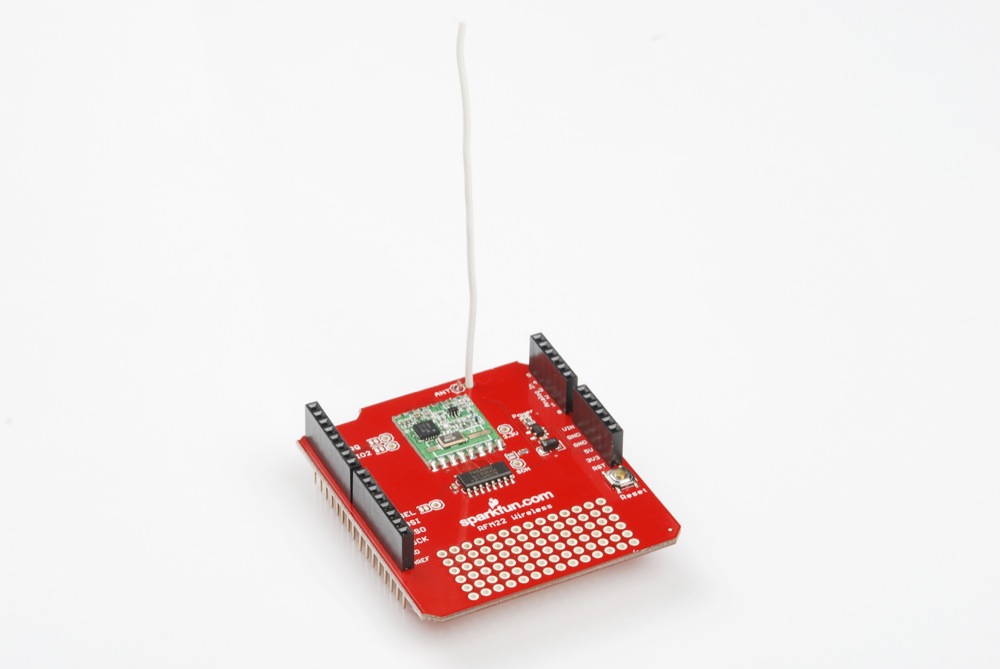
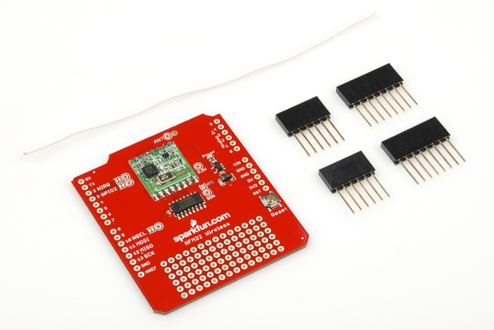
- 1 x pre-assembled RFM22 shield PCB. Compare to the picture above to make sure everything is in the right place.
- 2 x long-pin 1x8 female headers
- 2 x long-pin 1x6 female headers
- 1 x 5" wire (22ga solid)
If you find that anything's missing, drop our customer service folks an email and they'll help you out.
Next, you'll need to pull together the various tools that you need for assembly. All you need to provide is a wire stripper, a soldering iron, and some solder. You may find it handy to have a third hand tool or vise to hold the board steady while you solder. Our beginner's tool kit has everything you need in one place.
Assembly:
Assembly of the RFM22 shield is quite easy. The hardest part is getting the headers perpendicular to the board such that the shield plugs easily into Arduino boards, and other shields can be plugged in on top of it.
Start by placing the four header strips in the appropriate locations, by number of pins. The male pins should be sticking out on the side of the board with no components, and the female sockets should be visible when looking down at the component side. NB: at this point, if you have a known-good Arduino shield, you can plug it into the female side of the headers to hold them at a favorable angle and skip straight to soldering all the connections down. Be careful if you do that, though, because a small alignment error in the "good" shield will become a much larger error on the one you're soldering to now!
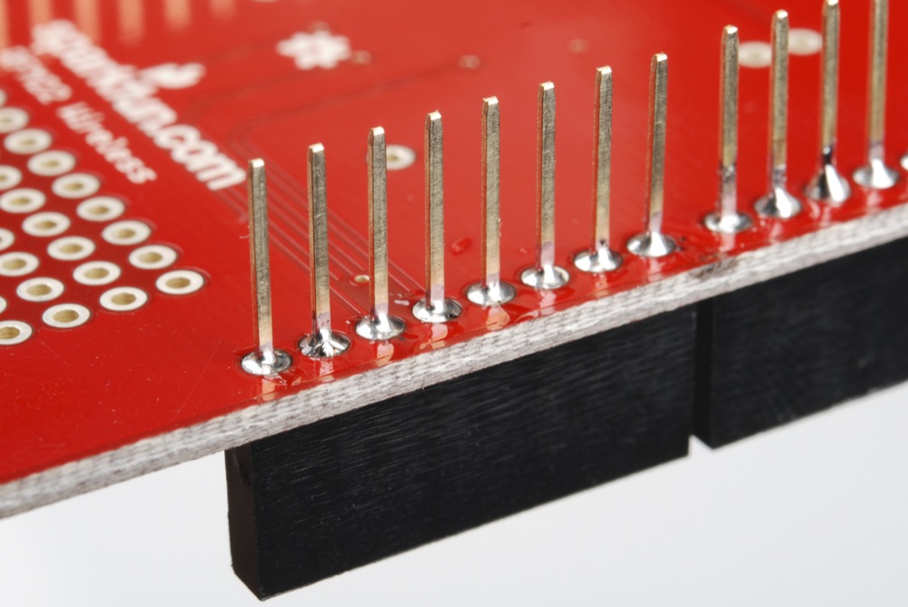
Flip the board over so the male pin side is up. This is the tricky part- the headers have a tendency to rock left to right, so that the end up soldered at a non-right angle with the board, which makes connecting other boards difficult or impossible. Tack down one and only one pin on each header.
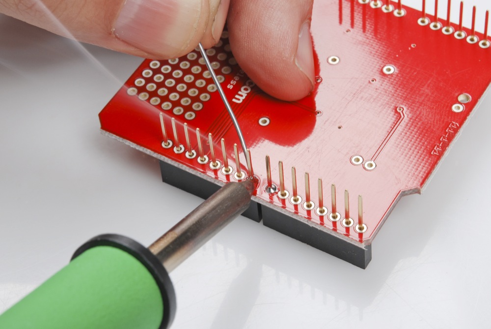
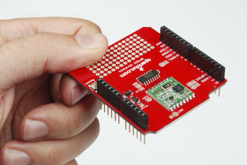
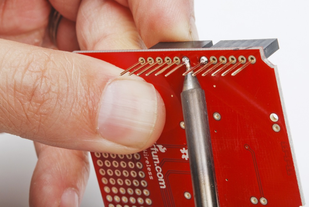
Now pick the board up. See how the headers stay in one place? That's great, because it's time to fit-check the thing. You can plug it into your Arduino board and see if goes in nicely; if not adjust any header that's at an inauspicious angle. To do that, hold the board as shown below and use your iron to melt the solder on the one pin that you tacked down earlier. Applying a little pressure with your forefinger on the female side of the header will cause it to sit flat on the board, most likely nice and perpendicular to the board. Make sure your fingers are not touching the pin you'll be heating!
Once all four headers are nice and square, set the board down again and solder the other pins. It pays to start soldering pins as far from the singles that you tacked down earlier as possible; that way, you won't accidentally melt the first one and cause the header to go all wobbly again before it's secured.
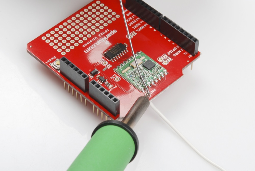
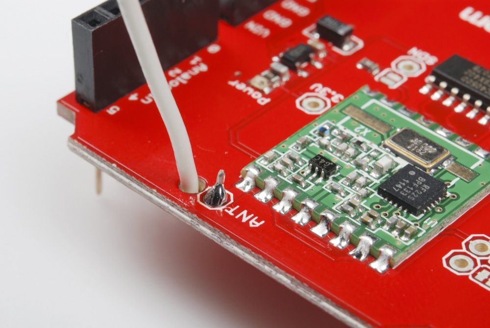
Next, you'll need to attach the piece of wire we've provided to the board. It will function as a 1/4 wavelength whip antenna; the radio module won't work properly without it. Start by stripping about 1/8" - 1/4" (3-6mm) of insulation off the end of the wire and threading the stripped portion up through the antenna hole as pictured below. Solder the wire to the pad as you would any other connection.
Once the wire is soldered in place, measure 8.3cm (3 1/4 inches) of wire from the underside of the board and snip off the excess. This tunes the antenna to 1/4 of the wavelength of the transmit/receive frequency (910MHz), which gives the best performance/size tradeoff.

Now thread the antenna back up through the strain relief hole and out the top of the board. You're done!
Using the RFM22 Shield:
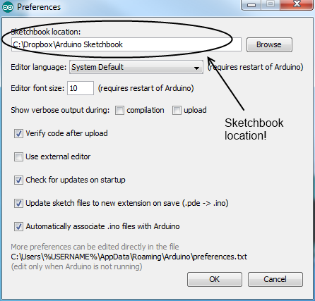
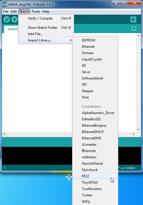
The RFM22 device is a little more complex than other "virtual wire" type wireless solutions. Fortunately, Mike McCauley has written a good library for the Arduino which can be downloaded here. Once you've downloaded the file, extract the archive and install it for Arduino by copying it into the "Libraries" subdirectory in your Sketchbook folder. You may have to create a "Libraries" directory. Find the Sketchbook location by checking in the "Preferences" window in the Arduino IDE; once you've placed the library in the directory, restart the IDE and you should see the "RF22" option under the "Import Library..." sub-menu in the "Sketch" menu.
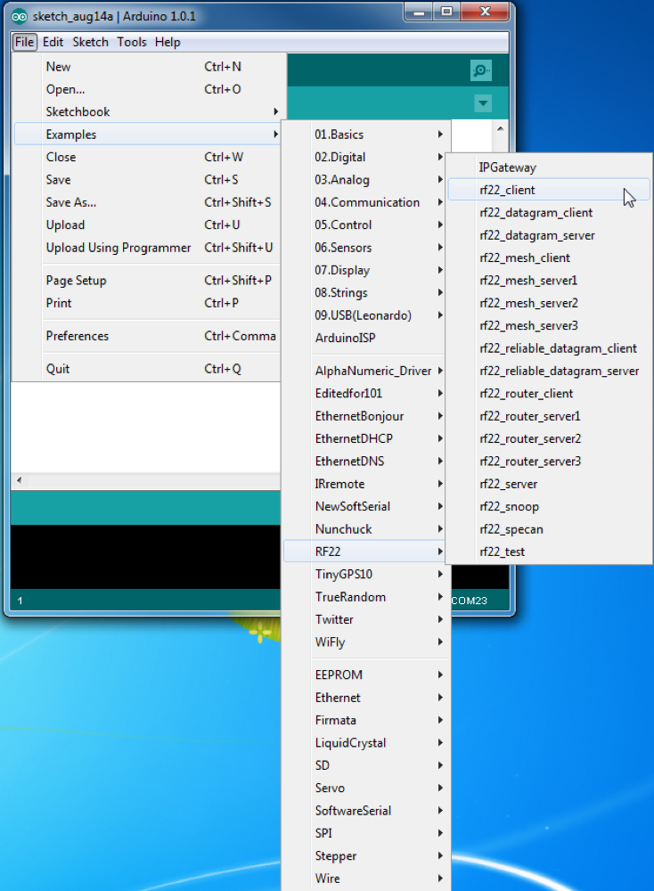
The library comes with a number of good examples; for our purposes here, we'll load the simplest ones: the "rf22_client" and "rf22_server".
Before we go any further, I want to point out that the more complex classes of the RFM22 module- RF22Datagram, RF22ReliableDatagram, RF22Router and RF22Mesh- are known to run poorly or not at all on ATmega328P based Arduino-compatibles (UNO, Pro, ProMicro, Duemilanova, etc) and none of the RF22 library support works on ATmega168 based boards (although those are only the very oldest of boards). At the time of this writing, support for Leonardo and other 32u4 based Arduino-compatibles (e.g., SparkFun's Promicro boards) has not been verified. Support is in place for Arduino Mega boards, however.
Okay, now that I've gotten that warning out of the way, let's go ahead and load up "rf22_client" and see what happens.
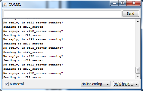
If there had been a failure of the RFM22 module, we'd see a complaint in the Arduino Serial Monitor (making sure the baud rate is set to 9600). As it is, the "No reply, is rf22_server running?" message lets us know that the sketch is running correctly, the library compiled properly and the module is communicating properly with the Arduino. Unplug this Arduino and plug in another one, with another RFM22 shield attached to it, and load the "rf22_server" sketch onto that board. Launch the Arduino Serial Monitor, and you'll note that there's no traffic at all. That's as should be; the sketch only prints messages received from an "rf22_client" device. Now plug in the other Arduino, the one that you already install "rf22_client" on, and watch what happens in the Serial Monitor window.
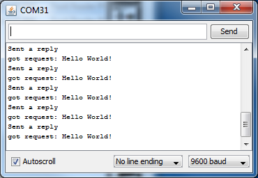
As soon as the new Arduino comes online- not more than a couple of seconds- you'll see a message start scrolling by indicating that the message "Hello world!" was received, and that a reply was sent. If you open the Serial Monitor to the "rf22_client" board, you'll notice a similar message:
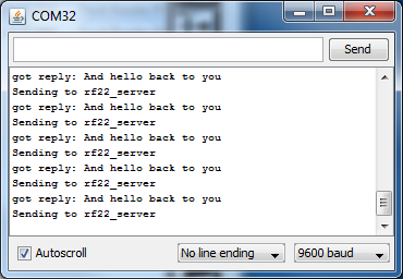
That message displays the text returned from the board programmed with the "rf22_server" example. Thus, these two examples show how to pass data back and forth between two devices and how to respond when a message has been received. For more information, check out the library webpage.
Important Legal Information:
The RF22 library downloadable from our site configures the RFM22 to operate at 910MHz. This is okay in the US and some other countries, but before you make extensive use of it in projects, please check your local regulations to ensure that it is not interfering with other local radio services. Note that the RF22 library as downloaded from the library webpage at open.com.au configures the device to transmit at 433MHz, which is not a generally acceptable frequency for use in the United States.
Next steps:
Now that you've got the boards up and running, and you've got some example code, enjoy the freedom to remotely deploy your Arduino products. Want to monitor activity in your chicken coop? Set up a weather station out at the edge of your property? Create a networked remote control system for your home entertainment system? The possibilities are endless. Make sure to let us know what you've created- we love hearing from you about your projects!
Actually, I am an amateur radio operator, callsign KJ1K, and I want to use it at 434 MHz. I would appreciate it if Member #412233 would contact me to give me the benefit of his experience with this product. Is there someway that members can communicate "off line"? If not, QRZ should work.
The link for the software now goes to a library that sets up a frequency of 434 MHz, so the antenna length should be about 17 cm, unless you figure out how to edit the software to change the frequency (I haven't got that far yet.) 434 MHz is part of the 70 cm ham radio band, so it's legal if you happen to have a ham radio licence, which I do, otherwise not really, at least in North America. If anyone knows how to change the frequency, perhaps they could add a comment, otherwise I will once I figure it out.