
Crazy Soldering
LCC packages are great if you are assembling 30,000 units. But can you hand solder an LCC package? Sure! Don't drink too much coffee before you go soldering 0603 parts, but it's actually not too tough.
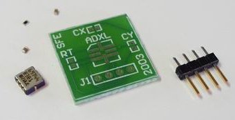
To assemble the ADXL breakout board, you are going to need a few things:
Soldering Iron:
You've got to have a good solder iron. If you paid $10 for it, you paid too much. What we mean is that if your soldering iron is cheap, it's really not going to work. We use a standard Weller WES50 soldering station. For around $110 you can't go wrong.
Soldering Tip:
Get a small SMT tip for your soldering iron. The WES50 came with the standard tip that is too large for SMT work. A nice small one (I can't find the part number) was around $5.
Two Caps, One Resistor - 0603:
The ADXL requires filtering capacitors and a timing resistor. READ THE DATASHEET. It's all in there. We used a 249k Ohm for a 2ms pulse width, and .01uF caps for 500Hz bandwidth. The PCB is made for 0603 size components.
Digikey Part #s:
311-249KHCT-ND - Resistor
399-1091-1-ND - Capacitors
4 Pin Header:
Easily obtainable - you may want to get the right angle type for a more compact board. We used a break away header found here.
Got it all? Good.
SMD Soldering -
We really can't explain how to solder, that's a tutorial unto itself. SMD soldering takes a steady hand, a good iron, and some tape or tweezers. Either look up some info on the internet, or ask a buddy. It's not hard, we just don't want to explain something you probably know by heart.
The Analog Devices' line of accelerometers are called ADXLs. These are tiny devices that contain a new technology called MEMS. Take a look on the Analog website to find out more.
If you know anything about variable plate capacitors, that's basically all the ADXL has inside. As the plates pull away from each other from acceleration forces (gravity) the capacitance changes. This change in capacitance is translated into a PWM signal.
Functionally, we use the ADXL to measure acceleration. For our discussion, we will focus on the ADXL202E dual axis accelerometer with +/- 2 gravity detection.
How to obtain: The ADXL202E can be readily obtained as a free sample from the Analog Devices website. They ship these things UPS next day air, so you should see it very quickly. Please don't go overboard with the samples - free samples are great - keep it that way.
Jameco also offers the Analog produced assembled evaluation board for $50.
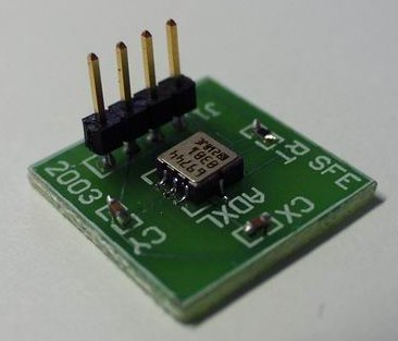
The LCC Package -
But now you've got a tiny ADXL contained in an LCC package. What now? (Warning: Sales pitch) Buy our ADXL header board of course! With this PCB you can hand solder the LCC package onto the PCB along with the two capacitors (for the dual axis ADXL202E) and the pulse width period resistor selector. The important pins are brought to a four pin header - GND, Power, X_Axis, Y_Axis. The ADXL can be powered from 3-5.25V and uses less than 1mA of power.
Capacitor and resistor selection is up to the end user. These selection devices are clearly laid out in the ADXL datasheet. We used a 249kOhm resistor and two .01uF caps to ensure a large bandwidth with a short pulse width. You may want to lengthen the pulse width if you are using a slower (4MHz) processor.
You've got the parts, time to solder them onto the PCB.
Da parts
You've got it all together - start from the middle and work your way out. The LCC package has a small dot on the bottom side.
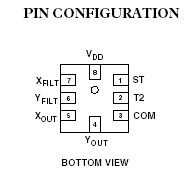
Pin Configuration
The dot is beneath the VDD pad needs to line up with the pad under the 'ADXL' label on the PCB. So Pin 1 (ST) lines up with the notch on the square on the board. This may be confusing because the above image is from the bottom view. Just take a minute and figure out where everything goes.
After you are satisfied you have everything oriented correctly, tape the sucker down.
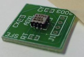
This is one of the ways we've found to create the "third hand". With an iron in one hand, and solder in the other, what keeps the parts from moving? Good old masking tape!

You'll want to get a good blob on the end of your iron so that you can heat both the LCC pad on the ADXL package and the pad on the PCB at the same time. If you've only got a dot on the side of the package that does not look like it flows to the pad, it probably doesn't. Re-heat the solder, add some flux and make sure the solder flows to the pads.
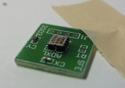
Now solder on the three components. We taped them down and soldered one end. Then pulled up the tape and soldered the other end. As you can see, our soldering job is so-so - our components have solder horns! Evil capacitors.
Viola
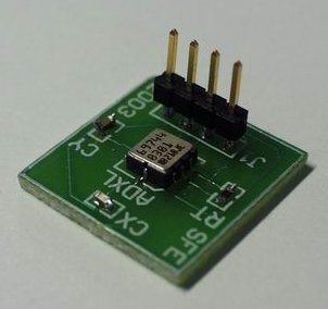
Finally, solder on the header. You may want to solder the header up or down based on your project (right angle headers are nice too!). We soldered ours straight up and on the front side to make the pictures look nice.
Not too shabby. Now compare this assembly with my buddy Pete's:
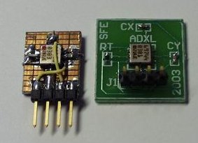
Sure, he's got me beat by size, but mine looks better - hah!
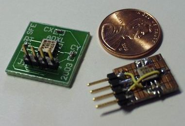
Either way, not much large than a penny and about the same weight.
Now we need to hook this thing into a bread board and get some data!
That was some fun soldering, no?
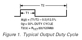
So you've got your board assembled (or purchased) and you are ready to go. The ADXL output Pulse Width Modulated signals. This may sound scary at first, but these signals are very easy to use. PWM is a standard encoding for many devices (IR transmitters, servo control, etc). In the case of the ADXL, the shorter the pulse width, the lower the gravity. A 50% pulse width corresponds to 0g.
As you tilt the sensor the pulse width will get longer on the X pin and shorter on the Y pin (or vise versa). This is the true beauty of the ADXL. Solid state tilt sensing is essential for input systems like floating mice and security devices.
To read the PWM of the ADXL it is best to start out with a counter that simply counts the number of cycles that the pulse is high. Here is some pseudo code to give you an idea of how to calculate the degree of tilt:
while(RC0 == 1); //Wait for current pulse to end
while(RC0 == 0); //Wait for low time to end
while(RC0 == 1) counter++; //Count the width of the pulse
Once you have this counter value the easiest way to display it is through a serial connection to hyperterminal. Output the value of the counter continuously as you tilt the sensor. You should see the counter change and reach maximum values for the various degrees of tilt.
The accuracy of the degree from level is not linear. Huh? You can measure many more little changes in tilt close to level. But as the sensor gets closer to vertical - the width of the pulses will change very little giving you less resolution as you approach vertical. This is a little confusing - check the datasheet - it's all in there.
You may want to deal with only the raw counter value rather than doing the intense mathematical conversions from counter values to degrees from level. This will save you processor cycles. Since floating point computations are pretty intense, just use the counter value directly.
What do we mean? Checkout our implantation of a tilt sensor into our glider!
Did this explain anything?????? WTF!
You have a point. The article says it is going to tell you how to solder LCC components and then does everything except that.
All the pic links are broken.
I have soldered this very part with a $5 solder iron. Tricky, yes, but doable.
I think the tip part number mentioned is ETH for the PES51 Iron. ETH is a 1/32" chisel tip. ;) Check out the great SMT soldering video on;
http://www.curiousinventor.com/guides/Surface_Mount_Soldering
I have that same tip on my WES51. Good tip for really fine pitch parts!
Might be a reasonanble idea for you to check which page number you are on for the article before you declare it finished and the tutorial useless.