How I Built a Cap Touch Sound Board with the Qwiic System
Marcus demonstrates how the Qwiic System makes it super easy to build a novelty sound maker with a capacitive touch interface.
Looking for a fun weekend project? You really just need a bunch of Qwiic-enabled breakout boards to tinker with.
In the Board Assembly department, we're churning them out as fast as our parts suppliers will allow! During my "day job" running the Pick and Place machines at SparkFun, I'm lucky to get to play with our 101+ Qwiic-enabled products every day, hot out of the reflow oven, and I've had this little project in mind for a while. I'd hesitate to call it a "keyboard" in the musical sense, given that the Qwiic MP3 Trigger only plays one track at a time (if you want polyphony, you're looking for the Tsunami Super Wav Trigger).
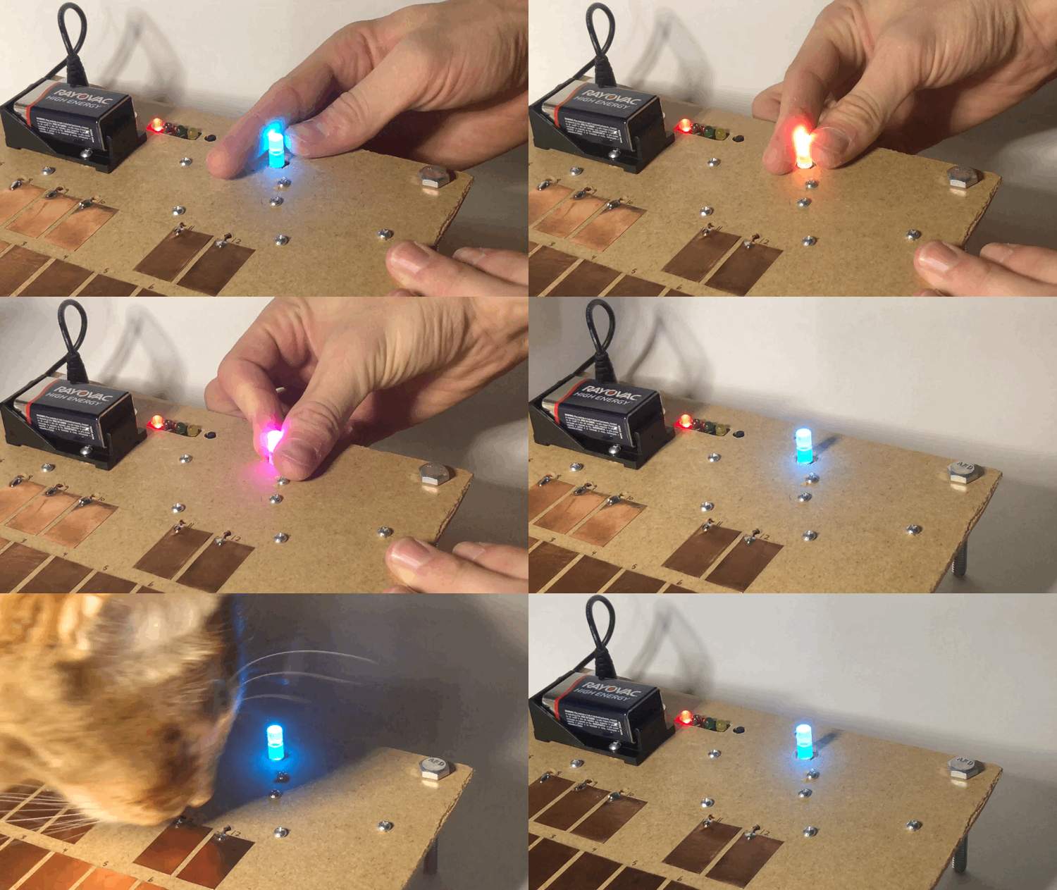
My Cap Touch Sound Board is exactly what it sounds like - just pop some MP3s on to an SD card and tap the copper pads to play back your noises. The added Qwiic Twist Rotary Encoder allows you to select from up to 84 MP3s (more if you modify the code), changing color depending on which group of 12 tracks is selected for playback.
If you want to build one for yourself, the parts are in the wishlist below:
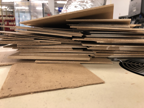
First, I grabbed a piece of the scrap MDF that we have laying around in piles around Board Assembly to use as a panel to mount everything on. If I'm correct, this is the third use this material has seen in its lifetime. We receive these thin fiber board panels as protective packaging in our PCB shipments, but if you look closely at some of the pieces, you can see where they have previously been used as a consumable backing during the PCB milling process (notice the grid of holes on the underside of my project).
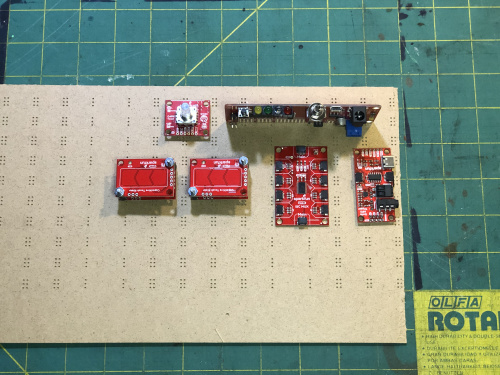
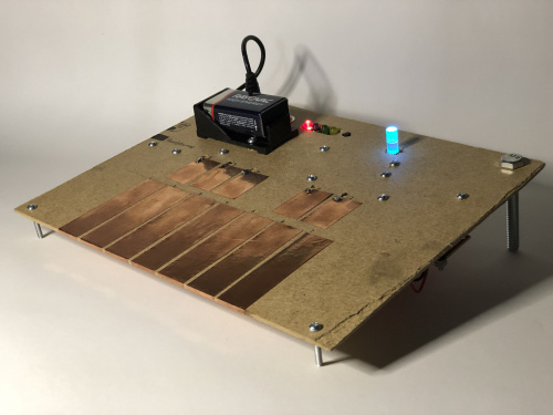
I got a rough idea of how I wanted everything arranged by simply laying it out on the panel and using a marker to mark where I needed to drill holes for mounting hardware. I also used this template to mark and cut out the holes for the RedBoard Edge (obviously the coolest RedBoard). I decided to mount the battery clip on the front side to take advantage of the barrel jack connector, and also so that all of the most commonly used features would be easily accessible. I did need to drill my own holes on the battery clip since the provided ones don't fit the hardware I'm using.
After settling on this layout, I used a utility knife to score the MDF panel and snapped it to the needed size. Then, I drilled the holes and mounted the electronics. One could connect all of the Qwiic cables first and then mount the electronics to the panel, but I've tried it both ways and mounting first is the way to go. I also drilled holes for some legs to hold the sound board up, which I made out of a couple 2-inch-long, quarter-inch bolts I had laying around. Then it was time to connect all the breakouts with Qwiic cables.
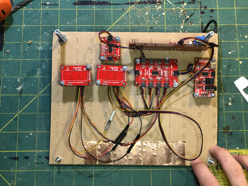
Here are the Qwiic connections:
- Redboard Edge ----> Main port on Mux Breakout
- Main port on Mux Breakout ----> Qwiic MP3 Trigger
- Port 3 on Mux Breakout ----> Qwiic Twist Rotary Encoder
- Port 4 on Mux Breakout ----> Capacitive Touch Slider #1
- Port 5 on Mux Breakout ----> Capacitive Touch Slider #2
- Port 6 on Mux Breakout ----> Capacitive Touch Slider #3
- Port 7 on Mux Breakout ----> Capacitive Touch Slider #4
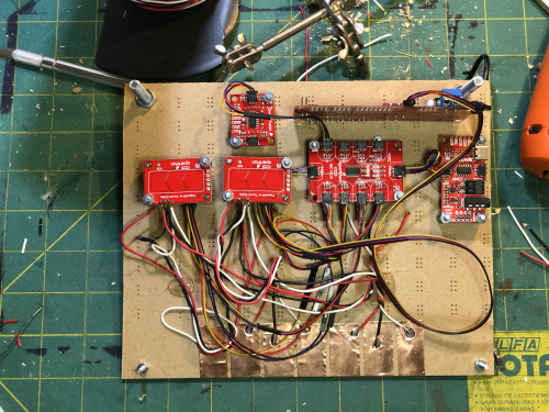
And here's what mine looks like:
You can see in the above Image that I also went ahead and cut twelve strips of copper tape to act as my cap touch pads on the front side of the project. For aesthetic purposes I arranged my pads like piano keys, but one could really do anything with the layout or shape of one's pads. The larger pads wrapped around to the underside of the project, but the smaller ones are floating, so I had to drill some holes next to these and feed jumper wire through to solder to each pad. Finally, after soldering jumper wires to each copper pad, I numbered the pads on the front side of my project and attempted to solder the jumper wires sequentially to the Cap Touch Slider breakout pins.
Here are the results of this attempt: (left pad, middle pad, right pad)
- Slider #1 ----> Pads 1, 2, 3
- Slider #2 ----> Pads 4, 5, 6
- Slider #3 ----> Pads 7, 11, 12
- Slider #4 ----> Pads 10, 9, 8
I knew I should have used some female headers, but I will just have to sort this out in code. Although it is imperfect, the hardware is now assembled and ready to load up an Arduino sketch. I made this little GitHub repo with the Arduino file and a bunch of sample MP3s to test the system out with.
Here's the sketch:
#include <Wire.h> //Needed for I2C

#include <SparkFun_CAP1203_Registers.h>
#include <SparkFun_CAP1203_Types.h>

#include "SparkFun_Qwiic_MP3_Trigger_Arduino_Library.h" //http://librarymanager/All#SparkFun_MP3_Trigger
#include "SparkFun_Qwiic_Twist_Arduino_Library.h" //Click here to get the library: http://librarymanager/All#SparkFun_Twist

TWIST twist;
MP3TRIGGER mp3;

CAP1203 sensor010203;  //cap slider connected to mux port 4, keys 1, 2, 3 (left pad, middle pad, right pad)
CAP1203 sensor040506;  //cap slider connected to mux port 5, keys 4, 5, 6 (left pad, middle pad, right pad)
CAP1203 sensor071112;  //cap slider connected to mux port 5, keys 7, 11, 12 (left pad, middle pad, right pad)
CAP1203 sensor100809;  //cap slider connected to mux port 5, keys 10, 9, 8 (left pad, middle pad, right pad)

#define MUX_ADDR 0x70 //7-bit unshifted default I2C Address

//Enables a specific port number
boolean enableMuxPort(byte portNumber)
{
  if(portNumber > 7) portNumber = 7;

  //Read the current mux settings
  Wire.requestFrom(MUX_ADDR, 1);
  if(!Wire.available()) return(false); //Error
  byte settings = Wire.read();

  //Set the wanted bit to enable the port
  settings |= (1 << portNumber);

  Wire.beginTransmission(MUX_ADDR);
  Wire.write(settings);
  Wire.endTransmission();

  return(true);
}

//Disables a specific port number
boolean disableMuxPort(byte portNumber)
{
  if(portNumber > 7) portNumber = 7;

  //Read the current mux settings
  Wire.requestFrom(MUX_ADDR, 1);
  if(!Wire.available()) return(false); //Error
  byte settings = Wire.read();

  //Clear the wanted bit to disable the port
  settings &= ~(1 << portNumber);

  Wire.beginTransmission(MUX_ADDR);
  Wire.write(settings);
  Wire.endTransmission();

  return(true);
}

void setup()
{
  Serial.begin(9600);

  Wire.begin();

  //Check to see if Qwiic MP3 is present on the bus
  if (mp3.begin() == false)
  {
    Serial.println("Qwiic MP3 failed to respond. Please check wiring and possibly the I2C address.    Freezing...");
    while (1);
  }

  mp3.setVolume(5); //Volume can be 0 (off) to 31 (max)

  enableMuxPort(3); //initialize qwiic twist
  twist.begin();
  twist.setCount(0);
  twist.setLimit(35);
  disableMuxPort(3);


  enableMuxPort(4);  //initialize cap touch sensors
  sensor010203.begin();
  disableMuxPort(4);

  enableMuxPort(5);
  sensor040506.begin();
  disableMuxPort(5);

  enableMuxPort(6);
  sensor071112.begin();
  disableMuxPort(6);

  enableMuxPort(7);
  sensor100809.begin();
  disableMuxPort(7);

}

void loop()
{
  int x = 0; //variable used to set track number w/qwiic twist knob

  enableMuxPort(3);

  if (twist.isPressed()){// stop the current playing mp3 when knob pressed
    mp3.stop();
  }

  int twistCount = twist.getCount();

  if(0<= twistCount && twistCount <5){//---------------> red = tracks 1-12
    twist.setColor(255, 0, 0); //red
    x = 0;
  } else if (5<= twistCount && twistCount <10){//------> green = tracks 13-24
    twist.setColor(128, 255, 0); //green
    x = 12;
  } else if (10<= twistCount && twistCount <15){//-----> violet = tracks 25-36
    twist.setColor(128, 0, 255); //violet
    x = 24;
  } else if (15<= twistCount && twistCount <20){//-----> yellow = tracks 37-48
    twist.setColor(255, 255, 0); //yellow
    x = 36;
  } else if (20<= twistCount && twistCount <25){//-----> pink = tracks 49-60
    twist.setColor(128, 0, 255); //pink
    x = 48;
  } else if (25<= twistCount && twistCount <30){//-----> blue = tracks 61-72
    twist.setColor(0, 255, 255); //blue
    x = 60;
  } else if (30<= twistCount && twistCount <35){//-----> orange = tracks 73-84
    twist.setColor(255, 100, 0); //orange
    x = 72;
  }
  disableMuxPort(3);


  enableMuxPort(4);
  if (sensor010203.isLeftTouched() == true) { //----------------> Key 1
    Serial.println("Touch1 left");
    mp3.playFile((1+x));
  } else if (sensor010203.isMiddleTouched() == true){//---------> Key 1
    Serial.println("Touch1 center");
    mp3.playFile((2+x));
  } else if (sensor010203.isRightTouched() == true){//----------> Key 3
    Serial.println("Touch1 right");
    mp3.playFile((3+x));
  }
  disableMuxPort(4);
  enableMuxPort(5);
  //bool reading2 = sensor010203.isTouched();
  if (sensor040506.isLeftTouched() == true) { //----------------> Key 4
    Serial.println("Touch2 left");
    mp3.playFile((4+x));
  } else if (sensor040506.isMiddleTouched() == true){//---------> Key 5
    Serial.println("Touch2 center");
    mp3.playFile((5+x));
  } else if (sensor040506.isRightTouched() == true){//----------> Key 6
    Serial.println("Touch2 right");
    mp3.playFile((6+x));
  }
  disableMuxPort(5);
  enableMuxPort(6);
  //bool reading3 = sensor010203.isTouched();
  if (sensor071112.isLeftTouched() == true) { //----------------> Key 7
    Serial.println("Touch3 left");
    mp3.playFile((7+x));
  } else if (sensor071112.isMiddleTouched() == true){//---------> Key 12
    Serial.println("Touch3 center");
    mp3.playFile((12+x));
  } else if (sensor071112.isRightTouched() == true){//----------> Key 11
    Serial.println("Touch3 right");
    mp3.playFile((11+x));
  }
  disableMuxPort(6);
  enableMuxPort(7);
  //bool reading4 = sensor010203.isTouched();
  if (sensor100809.isLeftTouched() == true) { //----------------> Key 10
    Serial.println("Touch1 left");
    mp3.playFile((10+x));
  } else if (sensor100809.isMiddleTouched() == true){//---------> Key 9
    Serial.println("Touch1 center");
    mp3.playFile((9+x));
  } else if (sensor100809.isRightTouched() == true){//----------> Key 8
    Serial.println("Touch1 right");
    mp3.playFile((8+x));
  }
  disableMuxPort(7);
  delay(0.2);//------------------------------------------------> pseudo debounce
}
With the MP3s loaded on my SD card, I clicked it in place, hooked up a little hamburger speaker for sound, and hit the power switch. Sometimes I have to hit the reset button to get things going, but once the Qwiic Twist knob is red, the Sound Board should be ready to play the first 12 tracks at the touch of a pad. Pressing the button of the Qwiic Twist will stop any currently playing song. Twisting the knob in either direction changes which songs are played when the pads are touched.
If you made it all the way to the end, thanks for reading. If you make this or another cool project using Qwiic enabled parts we'd love to hear about it!
