- Home
- Product Categories
- Infrared
- SparkFun Line Follower Array

SparkFun Line Follower Array
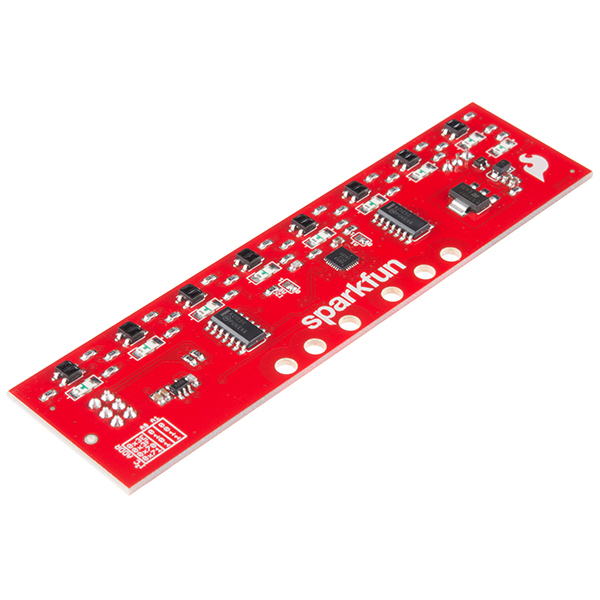
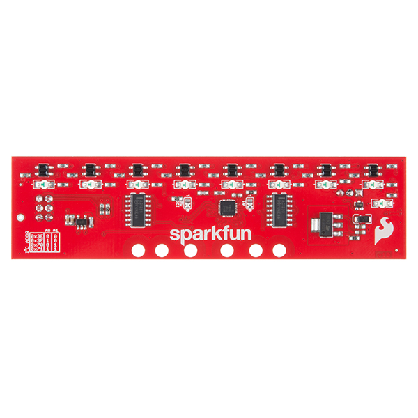
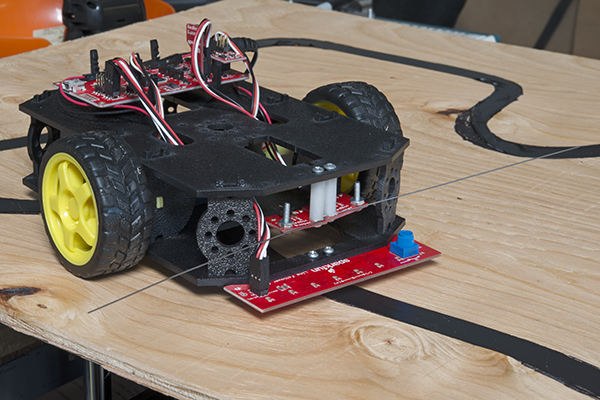
The SparkFun Line Follower Array is a long board consisting of eight IR sensors that have been configured to read as digital bits! We have designed the SparkFun Line Follower Arrays to follow a dark line of about ¾ inch width or smaller (spray paint or electrical tape) on a light background. Each array features visible LEDs that point upward when the board is attached (properly) so you can see what the robot sees, brightness control right on the board, and an I2C interface for reading and power control. Here at SparkFun, the RedBot Shadow Chassis was used as a test platform but really this was designed as an add-on for almost any bot.
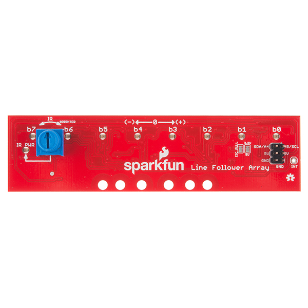
The line follower functions by taking an 8-bit reading of reflectance for use with following lines or reading dark/light patterns and can see from about 1/4 to 3/4 inches away. The IR brightness control and indicator can be adjusted with the on-board potentiometer and is capable of showing you the strength of the IR LEDs. Illumination can be turned on and off with software to conserve power, or left on all the time for faster readings. The SparkFun Line Follower Array requires 5V of power with a supply current range of 25-185mA with strobing disabled and 16-160mA with it enabled. Additionally we have added six mounting holes to the line follower with the two inner holes designed to fit our Shadow Chassis while the other four are general purpose.
Note: As you know our Sun emits quite a bit of infrared light, making the SparkFun Line Follower Array much less effective in direct sunlight. Plan your projects accordingly!
- 8 sensor eyes (QRE1113, like in our line sensor breakout)
- I2C interface
- Adjust IR brightness on the fly with a knob
- Switch IR on and off with software
- Switch visual indicators on and off with software
- Invert dark/light sight with software
- Based on the SX1509 I/O expander
- Schematic
- Eagle Files
- Hookup Guide
- Datasheet (QRE1113GR)
- GitHub (Design Files)
- GitHub (Library & Example Code)
- Product Video
SparkFun Line Follower Array Product Help and Resources
SparkFun Line Follower Array Hookup Guide
October 15, 2015
Learn how to connect the RedBot Line-Following Sensor Bar to an Arduino-type microcontroller. Use the example sketches to read data from the bar, and try out a simple line-following algorithm.
Core Skill: Robotics
This skill concerns mechanical and robotics knowledge. You may need to know how mechanical parts interact, how motors work, or how to use motor drivers and controllers.
Skill Level: Noob - You will be required to put together a robotics kit. Necessary parts are included and steps will be easy to follow. You also might encounter basic robotics components like bearings, mounts, or other hardware and need a general idea of how it goes together.
See all skill levels
Core Skill: Programming
If a board needs code or communicates somehow, you're going to need to know how to program or interface with it. The programming skill is all about communication and code.
Skill Level: Competent - The toolchain for programming is a bit more complex and will examples may not be explicitly provided for you. You will be required to have a fundamental knowledge of programming and be required to provide your own code. You may need to modify existing libraries or code to work with your specific hardware. Sensor and hardware interfaces will be SPI or I2C.
See all skill levels
Core Skill: Electrical Prototyping
If it requires power, you need to know how much, what all the pins do, and how to hook it up. You may need to reference datasheets, schematics, and know the ins and outs of electronics.
Skill Level: Rookie - You may be required to know a bit more about the component, such as orientation, or how to hook it up, in addition to power requirements. You will need to understand polarized components.
See all skill levels
Comments
Looking for answers to technical questions?
We welcome your comments and suggestions below. However, if you are looking for solutions to technical questions please see our Technical Assistance page.
Customer Reviews
4.6 out of 5
Based on 7 ratings:
0 of 1 found this helpful:
Good product, but needs better mounting options
The product works great, and is much easier to use than similar analog/digital arrays from other electronics component companies (the I2C connection is much more convenient).
It would be 5* if Sparkfun developed a 3D-printable adjustable mounting bracket for the array, since not everyone plans to use this on a small format toy robot chassis.
Nice sensor array
This was easy to setup and use. I was actually planning on making something like this when I found it, so thank you sparkfun for saving me some work. The potentiometer to set the brightness is nice and since it's I2C you can hook up multiple boards without using extra pins. The library was also very easy to use and it was able to do a good job of detecting a red line from about an inch away. Overall I'm happy with this board.
Easy to set up
Works great. Library made it easy to use, and I saved pins with I2C. It has 6 holes for mounting - I made my own bracket no trouble out of actobotics parts to mount to a line follower.
Works good
It works really well. You will have to play with the calibration knob a lot, and for initial testing its better to clearBarStrobe() to get faster readings and to see the state of the sensors, but so far I got my robot doing basic line following. Will work on more advanced next. As far as the mounting, I had to drill my own holes to use with my own robot, but it wasn't a big deal.
0 of 1 found this helpful:
Only follows black or white lines
nothing says that it will only follow black or white lines.. so it's kinda useless to me now
The sensor is based off of the IR reflective difference between the colors that it's looking at - you can run different colors, but they need to have a high contrast ratio for the device to be able to recognize it.
Very good for the price
Worked perfectly on the first try. Performed well. Very responsive.
For those who have struggled with mounting options or, like me, have damaged multiple arrays because they scrape against the floor and pop off the sensors, I asked a colleague of mine to remix a bracket from Thingiverse: http://www.thingiverse.com/thing:1278687
This one will support the line follower array and allows adjustable positioning depending on the height of the platform to which it is attached.
Thanks to Derrick Lingle for the design work.
Wow, that's really cool! I'll have to get one printed up for myself. Thanks for posting, and to Derrick!
can i apply fuzzy logic using sparkfun line follwer array
Dumb question: If I have a protective transparent plastic or glass shield, does that count as being "reflective"? I'm guessing that by adjusting the sensitivity I could "null out" any effects from this shield. Another interesting use for this could be monitoring an oil tank gauge. As the indicator moves up/down it would reflect on a specific photo sensor and give a digital read of the gauge.
I Just played around with a 1/8 inch piece of clear acrylic and was surprised. If the acrylic is clean and close to the sensors it seems to work at about 1/2 the distance, but the reliability goes way down. Slight changes in angle or scratches in the surface can throw it off.
If it's absolutely necessary that the sensor is protected, I would recommend a very thin sheet, or externally provided IR, and leave the setting to minimum so that the shielding material doesn't illuminate (like a light pipe).
The oil usage idea truely is interesting. I'm envisioning a 2-stroke scooter I had once. It had a sort-of translucent yellowish tank. Below the oil level it was pretty dark, so even though the plastic wasn't too clear, that may work.
Thanks for the info. I'm going to pick up this board next week and will try the light pipe approach although i'm thinking I might need to change out the IR leds with ones that have a "flat" top so they can mate correctly with the pipe, right?
I tried to do a line following robot in 1964 (6th grade) using some transistors, a flashlight bulb, and a photo censor. With an erector set chassis. Needless to say it didn't work quite as well as yours does. I believe the idea came from Pop Sci or a similar magazine.
DJ, WA9UBR
This is great! Transistors were relatively new at that time. Even though you didn't have super success, good work for trying! I couldn't get a transistor to cooperate until high school.
It's really interesting that you bring up popular science. A friend and I were recently discussing how the word "maker" is new but the concept isn't. I imagine old-time farmhouses where there wasn't great supply and people would work in their garages to make whatever they needed, they were the original makers. Magazines like popular science and popular mechanics were the equivalent of the internet.
This reminded me of a plan I got from my grandpa for the Bartlett flying Saucer, a hovercraft you could build and run with a lawn mower engine that was sourced through the back pages of popular mechanics. After 40 odd years in his shop drawer, I finally put the old plans to use while in high school. So it was OK I never got the transistor working right.
Thanks for comment! It's cool to hear this line following idea is more of a staple than I ever thought.
It would be nice if you demonstrated this product using a PID algorithm so the robot actually follows the line instead of herky jerky movements.
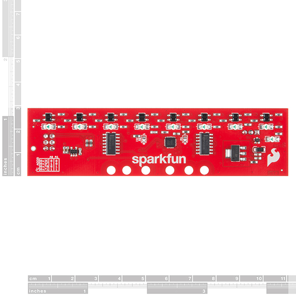
What's the dimension of the board ? (in mm and inches) What"s the spacing dimension between the sensor ?
Thkx.
Board is 4.2 by 1.1 inches (106.7 x 27.94 mm). Sensors are spaced 0.5 inches (12.7 mm) apart.