- Home
- Product Categories
- Development Tools
- 40 Pin PIC Terminal Development Board

40 Pin PIC Terminal Development Board
Replacement: None. We are no longer carrying this product in our catalog. This page is for reference only.
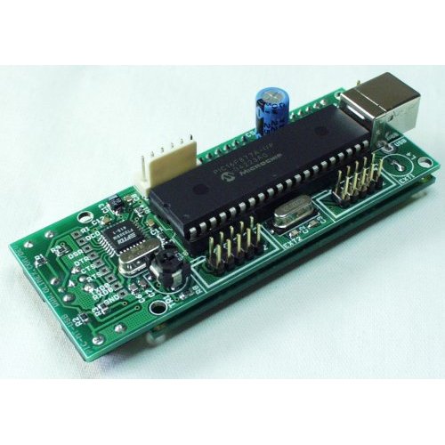
Want a serial LCD with some muscle? Maybe you just need a compact development board with a USB connection. This development board is what you've been looking for. The PIC-MT-USB uses a 40-Pin PIC at 20MHz, takes power from the USB port, communicates serially through the FTDI USB<->RS232 IC, interfaces directly to a backlit 2x16 character LCD, and leaves 16 general purpose IO pins for your wildest ideas.
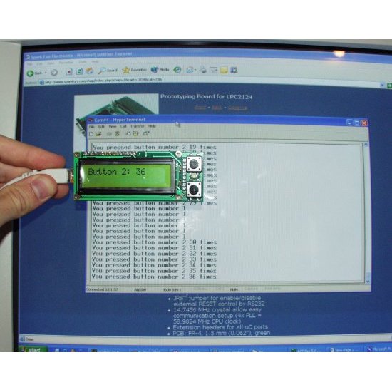
Take a look at the example code for a quick start into using the USB-Serial connection for directly printing to the LCD screen.
Note: This board uses the FT232BM from FTDI. Also, this board does not come with PIC installed. Please see a list of related ICs below.
- FR-4, 1.5 mm (0.062"), green soldermask, white silkscreen component print
- 20MHz crystal
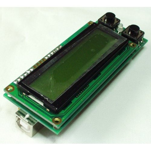
- LCD 16x2 alphanumeric display with backlight
- 2 Buttons
- Bi-color LED
- Power supply taken from USB port
- Virtual USB-RS232 port
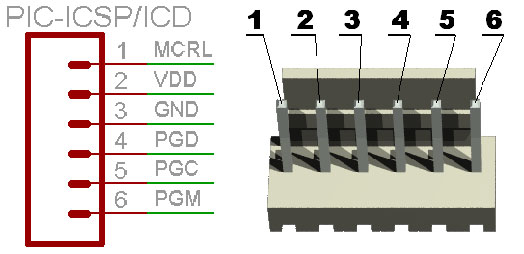
- ICSP/ICD connector for programming with PIC Programmers and Debuggers (for PICs with ICD support)
- DIL40 microcontroller socket
- Four mounting holes
- Extension headers for PIC unused ports
- 95x36mm (3.7x1.4")
- Schematic
- User Manual
- PIC ICSP connector
- Spark Fun MT-USB Example Code - Code to get you started with the LCD, buttons, internal EEPROM, etc.
Comments
Looking for answers to technical questions?
We welcome your comments and suggestions below. However, if you are looking for solutions to technical questions please see our Technical Assistance page.
Customer Reviews
No reviews yet.
Is this developpement code is compatible with different 40 pins PIC than the PIC16F887A ? Ex : PIC18F4450-I/P
Beginner question, just getting started with PIC micros. Bought this PIC-MT-USB and the recommended 16F877A. Would greatly appreciate if someone could provide basic step-by-step first time through instructions on how to load and run the MT-USB example code via the USB connection to Win7 PC (no RS232 port). Do I need to put a bootloader on the 16F877A first? If so, can I do that with the USB connection to the PIC-MT-USB?
Hi
This is the lcd controller
HD44780U
And here is a working code for this device:
http://www.ccsinfo.com/forum/viewtopic.php?t=24661
You have to change these pins to fit your this board like that:
#define LCD_DB4 PIN_D4
#define LCD_DB5 PIN_D5
#define LCD_DB6 PIN_D6
#define LCD_DB7 PIN_D7
#define LCD_E PIN_D2
#define LCD_RS PIN_D0
#define LCD_RW PIN_D1
And the LCD LIGHT is on PIN_D3
The code is for the CCS C compiler.
Amnon