- Home
- Product Categories
- LCDs and OLEDs
- Serial Miniature OLED Module - 0.96" (uOLED-96-G1GFX)

Serial Miniature OLED Module - 0.96" (uOLED-96-G1GFX)
Replacement:LCD-11315. 4D Systems has released a new revision of this product! This page is for reference only.
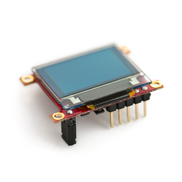
4D Systems' line of smart miniature OLEDs make it easy to add dazzling, full-color graphics and text to your embedded project. By incorporating their powerful GOLDELOX embedded graphics controller, 4D has taken the load off of your system. The uOLED board also has an on-board uSD card slot where you can store images, animations, icons, etc.
Two different firmwares are available from 4D Systems and either of the two can be loaded onto the GOLDELOX chip at any time. The GFX firmware is designed to act as a standalone microcontroller which you can program with the 4DGL language, which is similar to C. The SGC firmware configures the module to act as a slave processor, communicated via serial and handling only the graphics processing tasks while your favorite microcontroller does the external control.
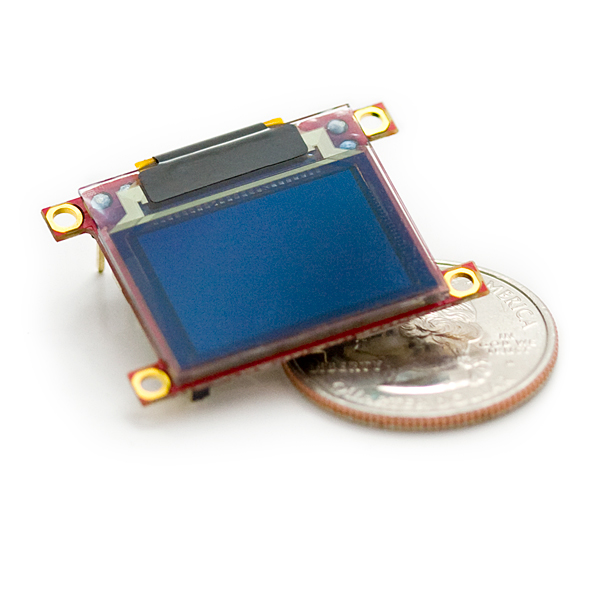
The uOLED-96-G1(GFX) is the smallest of the smart miniature OLEDs from 4D Systems measuring in with a .96" screen. Check out the 4D Systems product page for more information about the firmware options (PmmC) and how to swap them out!
Note: It's been brought to our attention that trying to program the 4D screens using an FTDI breakout can damage the driver. You'll need to use the FT232RQ USB to Serial which you can find in the related items below.
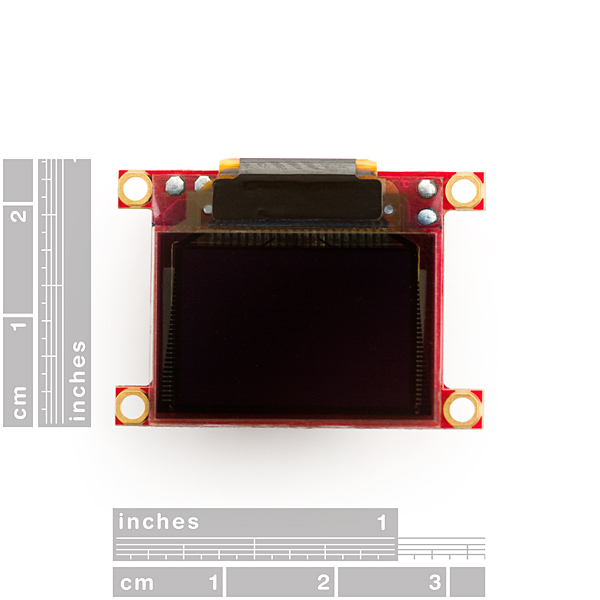
- 96x64 pixel resolution, 256 or 65K true to life colors Enhanced OLED screen
- 0.96” diagonal. Module Size: 32.7 x 23.0 x 4.9mm. Active Display Area: 20mm x 14mm
- OLED requires no backlight with near 180° viewing angle
- Easy 5 pin interface to any host device: VCC, TX, RX, GND, RESET
- Voltage supply from 3.6V to 6.0V, current @ 40mA nominal when using a 5.0V supply source
- Serial Interface (0V to 3.3V) with auto-baud feature (300 to 256K baud)
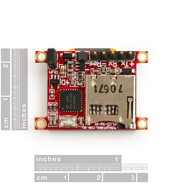
- Powered by the 4D-LABS GOLDELOX processor
- Module can be driven over serial (TTL) to USB adapter
- Onboard micro-SD (uSD) memory card adapter for storing of icons, images, animations, etc. (64Mb to 2Gb)
- Three selectable font sizes (5x7, 8x8 and 8x12) for ASCII characters as well as user-defined bitmapped characters (32 @ 8x8)
- Built in graphics commands such as: LINE, CIRCLE, RECTANGLE, TEXT, USER BITMAP, BACKGROUND COLOR, PUT PIXEL, IMAGE, etc.
Comments
Looking for answers to technical questions?
We welcome your comments and suggestions below. However, if you are looking for solutions to technical questions please see our Technical Assistance page.
Customer Reviews
No reviews yet.
This component may come loaded with one of two firmware packages. Either the GFX, or SGC versions. If its GFX, it will startup with a splash screen of tiny green text in the upper left corner. If its the SGC version, it will start up with a colorful splash screen that scrolls.
Serial communication with the display will NOT work unless the display is running the SGC version. So if you get this display, and it starts up with green text, you will need to connect a USB-to-Serial converter and run the 4d systems display firmware loader to reprogram the display to SGC before you can send it any information (including the auto baud rate detection byte).
I've been working on a new Arduino library for this display (and presumedly other 4D Systems OLEDs). It supports hardware and software serial, along with almost the entire SGC API. There are a few functions I've yet to implement (mainly joystick/sound/direct-image-drawing stuff) but for most operations it's pretty much complete. I'm adding to the library as I find useful features to implement.
Check it out on github: https://github.com/planetarian/4Duino
Can anyone report on the max frame rate this device supports? My application requires about 90 fps.
I've found that the display speed just depends on the operations you're performing. You don't have access to a frame buffer (unless you count the SD card), so working with the display is mainly a matter of sending draw commands. The more pixels that have to be drawn, the slower the display will respond and be available for further commands.
For example, the examples in my OLED library are quite smooth on this display, higher than my eyes can really discern, but those examples don't use screen blanking (the scope sketch blanks only a small area of the screen [two pixel columns]) and simply perform basic line draw operations. Another test sketch of mine which draws randomized objects to the screen doesn't seem to operate QUITE as smoothly, but is still at least 40-60FPS. A screen blank / background replace takes a fairly large fraction of a second by itself though, and you can visibly track its progress from top to bottom. So, if you need the display to be blanked after every 'frame' then it won't work for your application.
For those struggling to get this working with Arduino (like I did), here's how I finally got it to work:
I'm using Arduino 1.0 with a Duemilanove board.
First thing you need to do is that make sure you're running the right firmware on the display, I was running the wrong firmware, I thought I was running the right one, but there's apparently more than 2 versions so don't be lazy and make sure you go through the steps of uploading the right firmware, which is this one: https://github.com/pjkarlik/Arduino-OLED-Library/tree/master/PMM
(No that's not the lib I'm using - but that's the firmware file you need)
You upload that using 4Ds special tool.
Once you've done that, grab the library for the shield version of this board, here: http://code.google.com/p/displayshield4d/
Install in sketchbok folder as usual. Now to get this working with Arduino 1.0, you need to go into displayshield4d.cpp and change "WProgram.h" to "Arduino.h".
Now you should be example to run this example: http://code.google.com/p/displayshield4d/downloads/detail?name=displayshield.pde&can=2&q=
Make sure to connect TX to RX and vice versa from the Arduino to the display.
Since you can't have the display connected to TX/RX on the Arduino while uploading, you also need to do it like this: unplug TX/RX, upload sketch, replug TX/RX, hit the reset button on the Arduino. Now the display should turn green and a demo (the example code) will start shortly.
I hope this helps somebody.
I've been working on a (hopefully) easy-to-use library for this display, known to work on Arduino 1.0.1 with the Uno/Mega2560/Leonardo. Might be a good alternative to displayshield4d, especially since it has support for alternative Serial/SoftwareSerial interfaces. https://github.com/planetarian/4Duino
I am trying to get the library code to work that is from https://github.com/pjkarlik/Arduino-OLED-Library
I have everything working at this point, I can print a rectangle and circle and even single characters. However my DrawText function does not allow me to draw the text.
It seems to be hanging up the program and not letting it continue. Yet it does not error out when Compiling. I feel like it is how it passes my variable from mytext to the mytext inside the cpp file code.
Anyone else have any insight? I am passing mytext as an array.
Am I doing anything wrong?
What exactly do you need to do to start this screen
As I understand it to get this working you will need either USB to 5 volt serial or a RS232 to 5 volt chip like a Max232 and a 5 volt power source. The manufacture also sells a kit with the serial converter. Edit: The Serial converter needs to pull the reset pin low when the DTR signal is asserted.
Does anyone have any idea what library works with this OLED? I have tried every one listed in the comments, but keep getting errors. I am using Arduino 1.0 and a UNO board. Anyone? - EDIT... OK I guess I have to downgrade to 0.22 of the IDE for any of the libraries to work. Seems like no libraries exist yet for 1.0
ignore this post, the question it had is no longer relevant.
ignore this comment.
After agonizing over this screen for months and going through all the outdated or dysfunctional libraries available for it, I found one that works with the Uno / 328 and the most recent Arduino IDE.
The library is available at:
http://code.google.com/p/arduino-oled/
And I wrote up a basic Oscilloscope sketch for it that includes a trigger feature, it's posted at:
http://nodechomsky.com/post/3749787199/oscilloscope-for-arduino-and-4d-graphics-controller
and video of it in action (it's a bit blurry, but my camera is awful)
http://nodechomsky.com/post/3750164143/this-is-the-output-from-my-arduino-based-diy
Here's the serial command reference manual. I found this very useful, not all commands are supported, such as sound.
http://www.4dsystems.com.au/downloads/Semiconductors/GOLDELOX-SGC/Docs/GOLDELOX-SGC-COMMANDS-SIS-rev3.pdf
I wrote up a library for using this with an mbed (based off a library from someone else). If you prefer to use an mbed then you may wish to try this library.
mbed uOLED library
Another cool lib (under development) here:
http://code.google.com/p/displayshield4d/
Also check out this library: https://github.com/hugokernel/Oled4D
It supports NewSoftSerial, so you can use your uOLED next to other serial devices.
For an example of how these displays can be used see http://www.instructables.com/id/Arduino-Watch-Build-Instructions/
Also the Tutorial by Jenny is out of date, the current library that works with Arduino's can be found here. http://code.google.com/p/uoled-library/
I put one of these in a painting for a class and had it play videos I took while scuba diving whenever you walked up to it. It was connected to an arduino for control and had the videos stored on the uSD. They're pretty easy to use and there was a lot of detail in the videos considering how small the screen is. After that I attached another one to a pair of glasses to see what you could do with one of these guys as a stand alone computer with one of those sparkfun lithiums and a switch. The screen was pretty visible with a lens glued onto the glasses. I'm a big fan of these guys overall.