- Home
- Product Categories
- Components
- EL Sequencer

EL Sequencer
Replacement:COM-11323. We've pushed this board through a big upgrade! It now features zero-crossing optoisolated triacs and a 0.5A adjustable linear regulator. This page is for reference only.
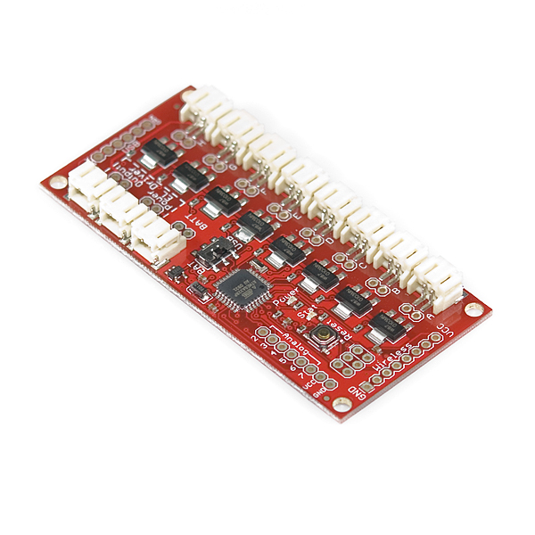
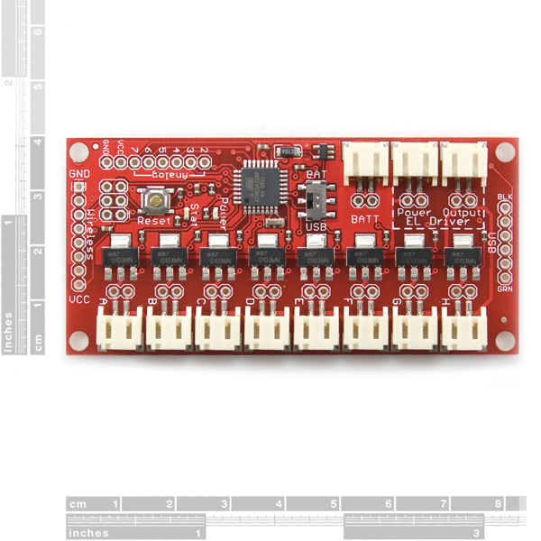
The EL Sequencer is a ATmega based control board that allows the user to program any sequence of blink, on/off, even PWM pulsing of EL wire. [
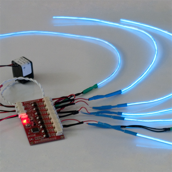
Electroluminescent wire](http://en.wikipedia.org/wiki/Electroluminescent_wire) is this really neat, flexible cord that emits a florescent light. Some times referred to as 'cool neon' because the cord does not heat up. The kicker is that EL wire runs on high voltage AC - about 125V at 425Hz. While EL wire requires very little power, you can't use normal transistors to turn on/off a string of it. So we created the EL Sequencer that uses TRIACs to control up to 8 channels.
What do I use this for? Checkout the demo video. You can have a lot of fun with EL! The demo video shows 8 strands of about 12" lengths of EL. The length of wire is arbitrary - you can have 100ft wires, it doesn't matter! Your inverter must be matched with the length of EL wire but it's not exact. I'm pretty sure we've got a 5-15ft rated inverter driving 12" segments. The inverter may not like it, but it works.
No really, what do I use this for? Oh! Oh, an example. Ok, checkout our tutorial on the Heartbeat Straight Jacket. It's a combination of EL wire and some fancy 2.4GHz wireless control. All built into a straight jacket for Burning Man.
Note: The schematic shows an ATmega168, but we are currently using the ATmega328.
- ATmega328
- Board can be powered from USB or LiPo
- Switch chooses source and acts as on/off
- Compatible with Arduino (8MHz LilyPad)
- On-board 8MHz external resonator
- TRIAC part #: Z0103MN
- 8 TRIACs can handle up to 600V
- Control 8 channels of EL
- Runs on 3.7V LiPo
- Footprint for connection to FTDI Basic for downloading code
- Footprint for connection to Nordic nRF24L01 2.4GHz wireless module
EL Sequencer Product Help and Resources
Sound Reactive EL Wire Costume
December 31, 2015
Learn how to make your EL wire costumes sound reactive in this project tutorial.
Comments
Looking for answers to technical questions?
We welcome your comments and suggestions below. However, if you are looking for solutions to technical questions please see our Technical Assistance page.
Customer Reviews
No reviews yet.
I got one last week. Here are my comments:
1. Please update your example code, it just doesn't work. The best example software is from Diana Eng, http://blog.makezine.com/archive/2010/04/programming_el_wire_fashion.html.
2. The Bildr Tutorial is really clear and everyone should probably look at it, is the only doc that shows how to connect the inverter(s) correctly.
3. When I tried to use the 3.3V inverter, it worked standalone, but not when driving the sequencer. It took a lot of current when connected to the sequencer and its output was zero. When the AC output was unplugged from the sequencer, it could drive an EL wire, as though the sequencer was shorting it. However, when the 12V inverter drove the sequencer, that worked fine. A mystery (to me, at least).
4. How do you dim the EL wires? PWM? I tried the "bit banging" method and that worked for a short while. Now most of the Triacs now seem blown out. Is it not ok to pulse the triacs at, say 1 KHz with a software-PWM method? My sequencer can now just turn on two of its outputs (the inverter and wires are fine).
5. Please include the right headers for the sequencer, kind of frustrating to get it and then not be able to program it without finding one. It is useless without some program, so I think everyone needs that header.
6. Suggest you include a default program, so that it will do something reasonable out of the box.
I am having the same problem with the 3.3V inverter!
This is probably due to the fact that I am measuring 230 VAC for the 3.3V inverter (without load) as opposed to the 12V inverter which only outputs 170VAC. Under load (i.e. with EL wire attached) they both go down to about 150VAC. It seems the EL Sequencer cannot handle the 230 VAC voltage, and the board seems to reset every time after trying to turn on the first EL wire. IIRC, the JST connectors are only rated for 100V but I am not certain if that is the root cause.
I did a little experiment which seems to confirm the voltage problem: I connected the output of the 3.3V inverter to the EL Sequencer "driver output", but I connected an EL wire in parallel as well. Because of that additional EL wire, which is always on, the "driver output" hovers around 150VAC when the El Sequencer is not driving any wires. The board works fine this way, although the brightness of the EL wires is reduced (due to the always-on EL wire in parallel)
I've had the same experience as this. It would be great to see example code and a video using the 3.3V inverter.
I had nothing but trouble with my sequencer. I also was using the 3.3 inverter. I never could get it to work with the sequencer. The inverter work fine when it was not hooked up to the sequencer.
*****************ISSUE SOLVED************************** Inverter Issue is related to the Ground wire, Ground on the board needs to be tied to the ground of the inverter source or the TRIACS will not work correctly.
Hope this helps, I found this out accidentally when I was probing with my voltmeter the lights would come on.
Its a little frustrating I burned out 2 EL wires due to arcing in the traces I induced by tapping the grounds together while troubleshotting.
I have the same issue - blew out almost all of the TRIACS after about 30 min of use! Very disappointing.
Unless I missed something, there is a major design flaw with this board. The HV ground of the traics is floating relative to the DC ground of the MCU. Essentially the HV ground can be higher and lower then the ground of the MCU. The "quick solution" at first might appear to be to tie these ground together......bad idea. The noise on the HV ground is going to be really bad. This is why the optocoupled triac drivers are needed. So in other words, this circuit needs to be scrapped.
This is also why people are having issues with program corruption and sporadic operation. Sometimes the "stars line up" and you won't have issues interfacing signals with grounds that are floating relative to each other. But eventually things will go bad. The reason pulsing the triacs eventually kills it is because there are various capacitances created by the various P-N junctions on the triac. Pulsing the traics is creating a AC drive signal that for all practical purposes, these capacitances are short circuits. If these caps are connected to a ground (HV Ground) that has floated lower then the MCU gnd, this is like connecting one of the pins of the MCU to -10...-12...-20V (I don't know the exact value that it floats).
I think I'm having this exact issue--I can't read from the analog pins and have El wire on at the same time, it hangs up the program loop, probably because of the noise on the circuit. When I print the reading back to serial out, it is definitely corrupted.
If your inverter behaves wildly because your there is no load, or if your loads are unbalanced (ie. you are switching between 6" of EL wire and 60' of EL wire) I found you can balance the loads using a capacitor in place of EL wire.
Capacitance of EL wire is about 1nF per foot, so if your inverter is rated for a minimum 20' and you are only driving a couple of inches of EL wire, you can put a 20nF cap across the inverter output to calm down the inverter. I believe it is behaving like a LC oscillator, and needs to be tuned to have a certain natural frequency.
Similarly in the case above, you can put a ~60nF cap across the 6" section of wire.
It would be great if you used a TRIAC with zero crossing detection. That way you could dim the wire by chopping the AC.
Hello,
I saw your board at maker faire, and I wanted to compare notes. (I built a very similar project for el-wire 2 years ago... used a PIC to make 8 channels, ganged a lot of pics together to make a 280 channel sequencer to light up the dome struts.)
Did you have any problems with your triacs? I noticed you didn't need snubber circuits or triac drivers / isolators.
Did you have any problems with the fading? I found that a high frequency driver (ie. 4kHz) would not fade as well as a lower frequency driver (ie. 1kHz) until I adjusted my PWM's to be all front loaded.
Anyway - nice project, I like the size... mine are significantly larger (through hole components)
Regards,
TJ
Hi Jack,
I am running into the issues you had addressed on the 4KHz PWM dimming. I would like some info on the snubbers you mentioned and the PWM fix. Do you have any pics on the big project you did? It sounds awesome.
I am trying to sync some dancers with Midi. Lots of problems so far.
Thanks
Rick
I ordered the El-Sequencer a few weeks ago and have been playing with it. It took replacing my board once and trying a few different things to get it working properly (mostly my own lack of understanding), so here are my experiences and recommendations.
You can find a more detailed document with pictures and my source code in my Git repository: https://github.com/charleslucas/EL-Escudo
I branched off the El_Escudo code, which supports fading, and also have included the code from Diana Eng's Fashion Blog which I had the most luck with. I've added cross-fading support and an example, and various #define options. Have been running the cross-fading code for about a day on eight strands.
I recommend soldering a wire to connect HVGND to VCC, rather than to GND as mentioned in the Bildr tutorial. I found this mentioned in a couple comments from people who seemed to know more about it than me, so tried it out and it works great. I refer to this as “inverted mode”, because it means you need to drive the output pins low to trigger the triacs. The original project source drives them high, so you will need to modify it, or use my source code and change the #define option in El_Escudo.h.
It ended up being easier for me, in a couple ways, to use two separate battery/power sources (one for the sequencer, one for the inverter). The upsides: - You can switch back and forth from 3V to 12V inverters as you see fit. - You can leave the FTDI connected to both power the board with the system running and re-program, while doing your development. If you use one power supply for both, you must unplug the inverter before re-connecting the FTDI to re-program, which can get tiring and give you more opportunities to hook the FTDI up backwards. The downside is that you end up with a lot of AA batteries to lug around. I suspect it's worth getting some LiPo batteries for a finished project.
Note: Do not plug your FTDI basic on backwards. It's easy to do this - my son did this while I wasn’t looking and fried the board, or at least the part that talks to the FTDI, and I had to order another. I recommend putting a sticker on the sequencer and the FTDI basic that matches up, or some way to make it foolproof.
This board seems to have numerous problems. One, for external drivers, it needs not a jumper, but a resistor between driver supply ground and driver output. The outputs are not isolated well, as I get crossover between channel patterns.
Can anyone recommend a good (wearable/carryable) enclosure for this board? I'm not seeing any obvious candidates.
Okay, so I am pretty confused with the board. I know that the inverter, battery and el wire is working (hooked up manually), but when I plug everything into the board it refuses to run. I have used multiple example codes (make magazine article, the one above, etc) and two different boards. Also, I have soldered a jumper between the two grounds. I am using this inverter: http://www.sparkfun.com/products/10201 this battery: http://www.sparkfun.com/products/339 and these el wires: http://www.sparkfun.com/products/10199 http://www.sparkfun.com/products/10195 What else can I try? Edit: The board does a blink test fine
I was able to get this going with ease for a project on my bike. I'm using a pretty hefty battery and the 12V inverter. Still working on how to mount the wires in a pretty way. EL Wire on a Bike The biggest problem I had was a lot of EL wire I previously had didn't use JST connectors.
Next, I need a project box that this should mount onto. Any suggestions?
hi...please help by mistake i connect el inverter wire in different port ( el power in driver output and driver output in el power ) i used 12v battery and now my el sequencer in not working but power led in working please help
I couldn't get this to work with the 3v Inverter, even though the inverter worked fine with a single EL wire plugged directly into it. In the end, I purchased this 3v inverter + power supply and it works just fine now.
Ok I'm just about to start a project and want to know about the inverter. Most sites say do not run the inverter with no wire attached. How do you do this with this board if all the 8 outputs are off does the inverter suffer?
Do I still need to link the ground to the inverter?
Cheers
nick
One solution is to put an unswitched load on the inverter ahead of the sequencer. This can be a length of EL wire (the minimum length specified for your inverter) if you want, but if you don't have any use for always-on EL wire, you can substitute a capacitor.
I was using a "Big Boy Classic" inverter, which has a minimum length of 20 feet, which is equivalent to about 30 nF (equals 0.030 uF) of capacitance plus some resistance. A 33nF 300V disc ceramic capacitor worked fine and cost only about $1. I measured the frequency coming out of the inverter and the capacitor had the same effect as 20 feet of EL wire. There's no need to simulate the resistance, just the capacitance. The capacitance required should scale linearly: 1.5 nF for every foot in the minimum length specified for the inverter.
Of course, this subtracts from the total capacity of the inverter. The Big Boy Classic is rated at 20 to 120 feet. So with the capacitor taking up 20 feet of capacity, that leaves 0 to 100 feet.
If you have an extra sequencer channel and a lot of faith, you can put the capacitor on an unused channel and program the sequencer to turn on that channel only when none of the actual EL wire segments is illuminated. This will work as long as you always have all the EL wire segments hooked up properly, and your software always does exactly what it's supposed to do. Too fragile for my tastes.
Actually, the ratings on inverters are somewhat optimistic. If you load the inverter to its rated maximum capacity, you will see reduced brightness. If your project switches between short lengths and long lengths (total of all illuminated segments), you will notice the difference. You can reduce this effect by using only half or so of the rated capacity of the inverter.
I bought 5 of these for a fashion show I was doing and after soldering them all and following the bildr tutorial closely, only one of them ended up working, so the rest I just ended up wiring straight to the inverter and using them as big expensive on/off switches. Does anyone know if the el escudo is better? Is there another alternative el wire sequencer? I love this product and just want it to work, but I think there's a trace that runs right by the soldering terminals that keeps getting screwed up, or maybe it's the triacs and these are just unreliable after all. Can someone, anyone (sparkfun?) help or provide suggestions because I really want to use these for future wearable electronics projects?
Hello, what do i need apart from the board to plug in usb to my computer ? Thanks in advance
I bought the el sequencer last year and had great results with my holloween costume. I used all 8 channels and had minor problems with shorting out here and there randomly. This year, I haven't changed anything except now 4 of the channels are running el tape. But now the board shocks me whenever i touch it, even disconnecting the el tape and running just el wire, same thing. If I barely shake the board, the reset button triggers and restarts my program. I even built a plastic housing to prevent anything from touching the outputs, but its very glitchy and pretty unreliable. Anyone else experiencing this? I followed all the tutorials on setting it up just like last year, like I said, everything is the same as before. Now that its 3 days before holloween, my costume is screwed! :(
I have ported (not that it was that complicated) the c library code into standard arduino code. I hope this might be useful for someone.
http://www.manofstone.com/teaching/elwire/
Be careful: the inverter input in this board is directly wired to the raw entry, if you look the schematic, raw is either the battery (~3.7V) or the USB bus (5V), depending of the position of the switch. However, the COM-10201 inverter below has a maximum operating voltage of 3.5V (according to datasheet), maybe with 3.7V is not so a problem, but be careful when you switch the board to USB and the inverter still connected.
We ran into an issue with the 3V inverter. Actually the two AC output lines were backwards. It seems there's a connection to ground inside the inverter, and hooking the inverter into the EL Sequencer caused a short. The AC voltage on the board at the EL Wire connections was something like 5 V AC, not 120 V AC.
Taking apart the JST connection on the 3V inverter and reversing the two black wires fixed the problem.
(To do that, use a flat screwdriver to gently press plastic tab on the the JST connection up to unlock the wires one at a time. Gently tug them out one at a time, then switch them and push them back in. Be gentle, don't force it. You may want to mark which wire is which with tape before beginning so you know if you've made a switch. You may want to use helping hands to hold the plastic JST casing and use needlenose pliers to pull out the wire.)
What's funny is that the hooking the inverter directly to the el-wire and batteries worked just fine. Thus, the unit passed QC.
@Sparkfun, you might consider adding a QC test to the inverters to check for the two black wires being reversed, as they are not interchangeable when used with this board.
Hope this helps someone else, this was a pain to debug for us!
You helped me and your timing was perfect. I was trying to get the inverter and the EL Sequencer working the night of the 13th with no success. Going back to these comments the next day saved me a lot of frustration; I'm a software time and not sure I would have found this issue without your post. Got back to this project today and everything works with your change.
Many Thanks.
Does the battery input have any kind of voltage regulator?
Can I use the 5v FTDI breakout with this board?
I just tried this successfully with the 5v FTDI breakout board. I would suggest looking at the post below from cjenkins where he suggests unplugging the inverter while using the USB power. It looks like the RAW input is connected directly to the inverter input.
I'm not sure if it's related or not, but the silk screening on the bottom does have 5v on the FTDI pin. Although it could be a mistake, since my 5v FTDI breakout board has 3v3 on the 5v pin :)
I'm guessing your FTDI board is putting out 3.3V. I'm using the 5V FTDI cable and it won't program...
This board does come with a bootloader burned to the chip right??
Well from what I heared, the Sequencer should have (just like the Arduino Pro) a voltage regulator that is able to handle up to 12 V (no guarantee). In the schematic it's marked as "U10" (in Arduino Pro schematic as "U2"). The Atmega328 chip can hadle up to 5.5 V (see Datasheet: http://atmel.com/dyn/resources/prod_documents/8271S.pdf), so a 5V Breakout should be no problem. Maybe the "Bildr Tutorial" will also help you.
I forgot, of course you need this:
http://www.sparkfun.com/products/9015
Are there any Eagle Files for this project?
I am working with and trying to learn Eagle Cad now, this would be a great board to start with.
Here's another little code snippet to share.
http://circle.twu.net/progs/EL2.tar.gz
It is a frame-based PWM that uses a buffer in PROGMEM for input. Designed to run at 10FPS (with clock drift, of course) it treats a byte as on/off state for each line and then does pulse width modulation to turn on more than 2 at a time at the sub-frame level so you don't have to worry about it.
It also includes a little utility program to convert any file into the data string to put into the code. 8-bit BMPs of fractals or music saved in WAV format will give you some pretty decent random patterns.
I have another program mostly done that uses Flash actionscript so that you can use elements in the timeline as inputs to generate the file but I ran out of time (leaving for BurningMan in a few hours) and slapped this together as plan C.
I'd written a much nicer library ( http://circle.twu.net/progs/Elvis.tgz ) that also does frame-based animation and pulse width modulation but it also eats up all of the RAM and you can't generate patterns more than 20 frames long. One could however probably pull code from this project and use it to generate the PROGMEM data for the other program if one desired.
This is all shamefully bad code cobbled together in about 2 days in last minute prep for burn, having never tackled arduino coding before so I apologize profusely for any shortcomings. I'll write something better next month.
-OS
I would avoid getting this product, it is terrible. The first one I got was DoA, and it took almost a month for me to get a replacement from sparkfun (and only a day or two of that was my fault, the rest was just waiting). I also had to regularly check up on the status, like you would on a 9 year old cleaning his bedroom.
The second one I recieved, while it works, i would barely consider it working. If I even look at it wrong, it resets. I can't run any of the examples from the EL Escucho library. If I try to turn all of the outputs on (with the function in the library), the board resets. This is a terrible product. See http://dorkbotpdx.org/blog/paul/sparkfun_el_sequencer_trouble for a list of more problems with it.
So it appears the triacs blow if you pulse them too frequently. It would be helpful if Sparkfun can give us some guidelines on how to prevent triacs blowing out so we don't have to find out the hard way. Anyone have any guidelines? Also, how do you balance the outputs if you leave some blank or have different lengths of wire.
Eagle files???
I am hoarding eagle files for most Arduino stuff, and knowing this is missing from my collection hurts. :-)
Having problems with this board? There's a great writeup here...
http://www.dorkbotpdx.org/blog/paul/sparkfun_el_sequencer_trouble
...explaining many of the problems people have and how to fix them. No idea if SparkFun is going to address the problems on the boards they have in stock or simply wait until they sell the current inventory, but I'm guessing the latter. Of course, they might never address the problems, so check out the webpage so you can do the work yourself.
Is there any documentation for the hardware that goes with this? I'm looking for pinouts of the connectors. Also, this is set up so I can use a usb to ttl converter and program it with the arduino software (as a lilypad), correct?
Where can I get more of the connectors? I'd like to be able to use ~3'-4' sections of el wire. I can cut it and solder a new connector on to it, yes?
http://www.sparkfun.com/products/8671
Hello, I want to set the intensity of each channel on el sequencer. Any clue on how to proceed? thanks
Oh, and I should mention that I followed the first bit of instructions at the makezine article (http://blog.makezine.com/archive/2010/04/programmingelwire_fashion.html) that bennard posted. The jumper did seem to be required for my sequencer (again, it's the 168 version) to work properly.
Here are the #defines I use now in the Arduino IDE.
#define DRIVER_A A0
#define DRIVER_B A1
#define DRIVER_C A2
#define DRIVER_D A3
#define DRIVER_E A4
#define DRIVER_F A5
#define DRIVER_G 8
#define DRIVER_H 9
After fighting and fighting and fighting with this board (I have the ATmega168 version) and the sample code I've seen, I busted out the meter and spent some time experimenting. mellis' code was helpful, but I am using the Arduino IDE and couldn't make TRIACs A-F work. G and H worked fine.
So -- for the ATmega168V version, at least--I found the mappings: TRIACs A through F are to mapped to pins A0-A5, and G and H are mapped to digital pins 8 and 9. If I use those mappings, everything works fine, including using A-F at the same time as G and H.
Mappings, then, would be:
A - A0
B - A1
C - A2
D - A3
E - A4
F - A5
G - 8
H - 9
Right now I have three 3m EL wires connected to D, F and G, and this code works for me:
define DRIVER_G 8
void setup()
{
pinMode(DRIVER_G, OUTPUT);
pinMode (A3, OUTPUT);
pinMode (A5, OUTPUT);
}
void loop ()
{
digitalWrite (DRIVER_G, HIGH);
digitalWrite (A3, HIGH);
digitalWrite (A5, HIGH);
}
Hi is it possible to control dimming in the 8 channels individually with the el sequencer?
The inverter indicated for this product behaves wildly when unloaded, it is recommended that a dummy load (a length of el-wire) be used pre-triac to keep the output sane and not blow triacs.
n/m the comment I posted above. I found the arduino libraries listed under the el escudo. Okay, I have a new question. I cannot get my bluetooth 'mate' to connect to this sequencer. The red light that indicates power is flowing into it (bluetooth mate) doesn't even light up. Why???? thanks!
Have you found a solution to this problem?
Thanks
Is there wiring (arduino) example code? I need to be able to fade the el wire on and off. It doesn't look like this sequencer has analog outputs....
I have the board set up and working for lighting el wire. Now the next step, is I want to interface with a Sparkfun product, the Midi Shield Tx output. I'm thinking I can do this via the El Sequencer "Analog" inputs, how can I set those pins up in the code to receive information from the Midi Shield and to give a variable so I can do a "while-for" ?
Any help or tips would be greatly appreciated. Thanks!
A few notes on what it took to get me going on this. First, I found that the chip I got with this sequencer was actually the ATmega328P rather than the ATmega168V. Get a bright light and a magnifying glass and double check your chip to make sure you know what you've got. Its important for avr-gcc when building the code and for avrdude when programming the device.
Secondly, thanks @mellis for the corrected code. This gets the sequencer lighting the wire were the original did not. I noticed however, that the 'line_on' and 'line_off' functions were inverted for me, i.e. 'line_on' actually turned off the wire and 'line_off' turned it on. Also there is superfluous code in those functions to turn off the last lit line. I was confused why this was necessary and my setup has worked just fine without it.
Finally, I noticed that avr-gcc doesn't recognize atmega328p as a chip name but will accept atmeta324p and build a compatible binary. Avrdude still needs 'atmega328p' however, so my Makefile is a bit hacked up now. I thought maybe I had an old avr-gcc but after an update I still had the issue.
What are the inputs, do they accept logic on and off? Can I control the El Wire outputs based on this logic? I'm interested in using a midi decoder, to use a midi controller or ableton to control the El Wire. http://highlyliquid.com/kits/md24/
I'm not interested in programming code, I'm interested in the El Wire being midi controlled, if this isn't the item to do that, perhaps you could direct me to a sequencer which would have basic logic controls.
Thanks
The "analog" header on the board goes to unused I/O pins on the microprocessor. By rewriting the code you can have it do whatever you want based on the inputs from (or send outputs to) those pins.
These pins are labeled "analog," but they could easily do digital I/O, it only depends how they're defined in the software.
The example code doesn't seem to match the pins used in board. I had to make a few changes to get it to work. Corrected version here: http://forum.sparkfun.com/viewtopic.php?f=14&t=22710
Thanks for posting this up. We will look into to this to see if there is a mistake, or a revision needed.
i used this board to make a mind-blowing EL light-suit. It worked perfect for a couple hours at a rave and then it stopped. Reset and power cycling did nothing. I had to upload the code to it again and then all was well.
Is there some common reason for the program to get corrupted? I admit my program "works" but is sloppy. So either the inverter sent some pulse somewhere or I had some number turn over and flip some bit somewhere, wiping out the program.
No there isn't any obvious reason the micro would stop working all of a sudden (other than radiation from the lumineferous ether).
At first I would say there was a fuse bit issue, but reloading code wouldn't change the fuse bits.
I'm chalking it up to firmware integrity.
thanks for the reply.
ive been trying to recreate the corruption for the last two weeks. no luck. ive gone over the code in detail and cant find anything wrong.
best i can figure is that i spilled some drinking water or sweat on the board and was gently shorting something, and then one of the times it was turned on it went into programming mode with noting to load.
it is, at this time, working perfect.
Would it be possible to run cold cathode tubes off this board? It looks like standard 12" computer case tubes come with 680v inverters which looks to be just over the voltage that the triacs can handel. Did I just awnser my own question?
Any help would be appreaciated thanks
Im thinking would it be possible to replace the Z0103MN triacs with the Z0103NN to handel up to 800v?
I have one of these. LOVE IT. I was having all kinds of trouble getting mine to work. Then I figured out what i was doing wrong from reading this website:
http://blog.makezine.com/archive/2010/04/programming_el_wire_fashion.html
The two things were:
1. A-H are just the Arduino pins 2-9. So code it like a regular arduino project using 2-9 as outputs.
2. For some reason i needed a jumper between the grounds on the El Driver box, from power to output. I dont know why, but the above example had it and it made everything work fine. Look for the big blue jumper wire in the middle of the page. Con someone comment on this jumper??
Im using 'lilypad arduino atmega328' for the 'board'
Can someone explain what the AIN (Audio) pin is for and how to use it? To my novice eyes, it appears there is a pull-up resister on this pin and a high-pass filter (0.1uF cap) in series connecting it to one of the ATMega's ADC pins.
Personally, I would like an accessible ADC pin to connect one of sparkfun's amplified microphone break-out boards (either the MEMS or Electret version) and then run an FFT like this:
http://tinkerish.com/blog/?p=39
Zach
Here is a project I did with the EL Sequencer controlled via an iPhone or iTouch and a WiFly module.
http://www.projectallusion.com/1/post/2008/10/iphone-controlled-electro-luminescent-suit.html
this video link needs a password :(
Here's some cheap EL wire- http://www.goldmine-elec-products.com/products.asp?dept=1290 You just have to get your own leads on it.
Hmm, I'm confused. Your "Compatible with Arduino" feature above seems to imply that you can program this via the Arduino software.
But on the Sparkfun forum at http://forum.sparkfun.com/viewtopic.php?p=76091&highlight=#76091 it looks like that's not the case. Is there really no way to program one of these puppies with the Arduino IDE that I've grown to know and love (or at least be comfortable with).
Hi,
Looks very interesting so I'd like to see the video. But Vimeo says the video is a private video.
http://www.vimeo.com/4754275
Could you please change the option if possible?
Best,
Shigeru
Oops! Sorry Shigeru. Fixed now.
I have this board powered as per the bildr tutorial. That part seems to work just fine, but... I wrote a simple on/off sample which worked for about 30 seconds or a minute, and then suddenly one of the channels goes into perma-ON mode (dims a bit based on load on other channels, but otherwise ON). I have disconnected everything and reconnected, re-uploaded code etc. Still has same issue (Channel G). Is this board just really low quality, or is it issues with the triacs as some have suggested? Any tips on how to troubleshoot this?
Best,
Max