- Home
- DigiXTend Modem Breakout

DigiXTend Modem Breakout
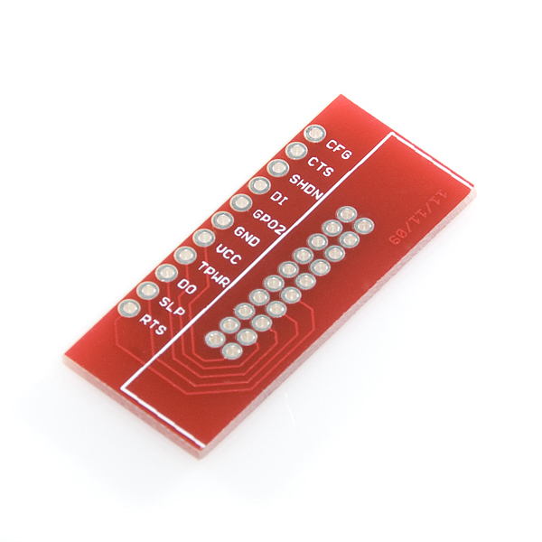
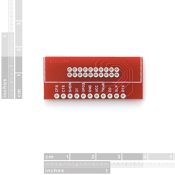
This is a simple breakout board for Digi's XTend 900 Modem. This board breaks out all eleven of the pins used by the modem to a 0.1" pitch header. Make sure you connect the XTend modem on the correct side of the board, as indicated by the silkscreen.
This product is only the PCB, no headers will come installed. Soldering a couple 10-pin/2mm XBee headers in will allow you to easily connect and disconnect your XTend modem.
DigiXTend Modem Breakout Product Help and Resources
Core Skill: Soldering
This skill defines how difficult the soldering is on a particular product. It might be a couple simple solder joints, or require special reflow tools.
Skill Level: Noob - Some basic soldering is required, but it is limited to a just a few pins, basic through-hole soldering, and couple (if any) polarized components. A basic soldering iron is all you should need.
See all skill levels
Comments
Looking for answers to technical questions?
We welcome your comments and suggestions below. However, if you are looking for solutions to technical questions please see our Technical Assistance page.
Customer Reviews
No reviews yet.
The person who made the xtend library part made it in reverse. he left-right [horizontally] flipped the pins. Thanks, now my 12 PCB's i let made are useless. Omg. +1000 points for having a library in the first place, but man, don't just copy the datasheet (which looks at the module the other way around).
The silkscreen is oriented so that it faces down when attached to the Xtend modem
Thanks! You quite literally just saved my project!
I didn't catch that either in the sparkfun Eagle library... fortunately I could mount the connector on the bottom of the board and plug in the XTend radio, which worked. After having several such surprises from random Eagle libraries I get from the Internet, I now am more careful about verifying pinouts on new parts.
Hi Sparkfun ,
Good to see you guys carrying this product on your product line. But the problem is that the DIGI Xtends come with a strict warranty statement, that says if we solder anything on to the modems directly we void the warranty.
So it would be good if you sell the break outs with accompanying headers of that pitch, so that customers jut plug their units on to this breakout and don't void their warranties by soldering anything on the modems.
Keep up the good work.
Somnath
Not the brightest bulb in the shed :) this is a separate PCB module; so you do not do anything with the modem. But indeed i totally agree SF should just give you a 2row-2mm pitch with this at least. its pretty hard to get 2 lines of 10 properly in straight, since its such a small unit. But ofcourse i managed.
As said above, "This product is only the PCB, no headers will come installed. Soldering a couple 10-pin/2mm XBee headers in will allow you to easily connect and disconnect your XTend modem."
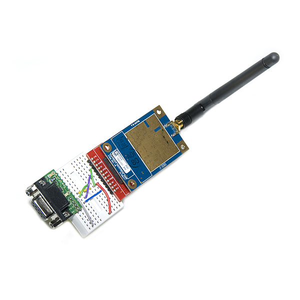
Hello sparkfun .. can anybody please tell me how to connect the xtenda to the breakout and then how to connect it to arduino Uno i'm totally new to RF .. thank you so much
Using two 10-POS 2mm Xbee headers soldered side by side as suggested in the product description does not work correctly. You really need a 20-POS (2 row x 10-POS ) 2mm female header otherwise you will bend the on-module male header pins' rows significantly outward (not a good idea).
100% agree. I wish I'd seen this before I started soldering. I got the two 10 pin headers on straight, but I'll certainly bend the pins (or worse) on the radio if I try to plug it into the headers.
Any suggestions on equipment to use to solder the very fine pins of the header onto this breakout board? the modem module cannot be soldered directly as that voids the warranty.
I've personally used a large hoof tip and an iron without an issue. They aren't that small. Just don't drink too much coffee beforehand.
the tracks for VCC and GND could have been made thicker considering this is a 1 watt transmitter !!