- Home
- Product Categories
- PTH ICs
- LED Display Driver (8-Digit) - MAX7219CNG

LED Display Driver (8-Digit) - MAX7219CNG
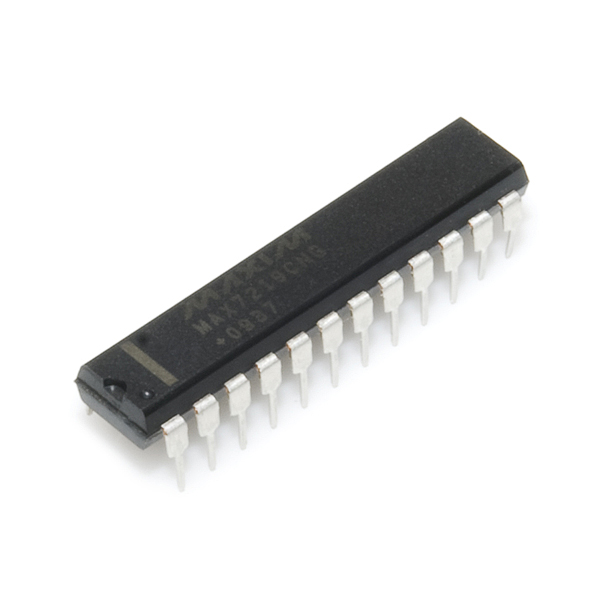
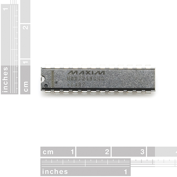
The MAX7219CNG is a compact, serial input/output common-cathode display driver that can interface microprocessors to 7-segment numeric LED displays of up to 8 digits, bar-graph displays, or 64 individual LEDs. Included on-chip are a BCD code-B decoder, multiplex scan circuitry, segment and digit drivers, and an 8x8 static RAM that stores each digit.
Communication with the MAX7219 is achieved through a convenient 4-wire serial interface (supports SPI). Individual digits may be addressed and updated without rewriting the entire display. Only one external resistor is required to set the segment current for all LEDs.
The IC also includes a 150μA low-power shutdown mode, analog and digital brightness control, a scanlimit register that allows the user to display from 1 to 8 digits, and a test mode that forces all LEDs on.
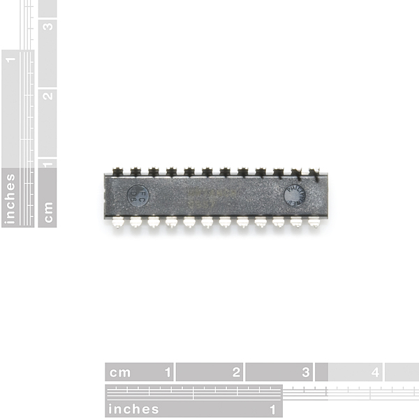
This device comes in a 24-pin DIP package.
- 10MHz Serial Interface
- Individual LED Segment Control
- Decode/No-Decode Digit Selection
- 150μA Low-Power Shutdown (Data Retained)
- Digital and Analog Brightness Control
- Display Blanked on Power-Up
- Drive Common-Cathode LED Display
- Slew-Rate Limited Segment Drivers for Lower EMI (MAX7221)
- SPI, QSPI, MICROWIRE Serial Interface (MAX7221)
- 24-Pin DIP package
LED Display Driver (8-Digit) - MAX7219CNG Product Help and Resources
Core Skill: Soldering
This skill defines how difficult the soldering is on a particular product. It might be a couple simple solder joints, or require special reflow tools.
Skill Level: Rookie - The number of pins increases, and you will have to determine polarity of components and some of the components might be a bit trickier or close together. You might need solder wick or flux.
See all skill levels
Core Skill: Programming
If a board needs code or communicates somehow, you're going to need to know how to program or interface with it. The programming skill is all about communication and code.
Skill Level: Competent - The toolchain for programming is a bit more complex and will examples may not be explicitly provided for you. You will be required to have a fundamental knowledge of programming and be required to provide your own code. You may need to modify existing libraries or code to work with your specific hardware. Sensor and hardware interfaces will be SPI or I2C.
See all skill levels
Core Skill: Electrical Prototyping
If it requires power, you need to know how much, what all the pins do, and how to hook it up. You may need to reference datasheets, schematics, and know the ins and outs of electronics.
Skill Level: Competent - You will be required to reference a datasheet or schematic to know how to use a component. Your knowledge of a datasheet will only require basic features like power requirements, pinouts, or communications type. Also, you may need a power supply that?s greater than 12V or more than 1A worth of current.
See all skill levels
Comments
Looking for answers to technical questions?
We welcome your comments and suggestions below. However, if you are looking for solutions to technical questions please see our Technical Assistance page.
Customer Reviews
4.7 out of 5
Based on 6 ratings:
Versatile and easy to use.
I've breadboarded this with some LEDs and used it with the Arduino library, and it worked fine the first time. It'll drive discrete LEDs or 7-segment displays and do the 7-segment decoding for you. No visible flicker when multiplexing. I'm currently building one into a proton pack!
My introduction to ICs
Wanting to build and control an 8x8 matrix of LEDs, I set about learning how to use an Arduino. I'd already been a little proficient with programming, but had hardly any experience with circuitry.
This was the chip which let me get the grid working! It was my introduction to circuit schematics/diagrams and dealing with calculating V=IR. Wasn't nearly as bad as I had worried it would be, and now I have a nice little matrix as a toy I built (planning on putting 4 of these together for an eventual 16x16).
This chip works beautifully. Nice libraries for support with the Arduino, and many tutorials for guiding the lost (of which I was one).
Anyone interested in seeing my project unfolding: http://acressity.com/arduino
it's great
This driver works great for multiplexing led projects. Currently working with it on a project with 8x8 led matrices, so I'm looking to daisy-chain 2 of the 7219s to drive 2 matrices.
No problems!
My last couple of these (from a different vendor) died after a very short while. The ones I've purchased from here are doing great (so far)!
Timely and Working
parts got here promptly and worked perfectly.
When you hook these up, dont forget which pin you wired to the +5V and which you wired to ground.
When you switch them, the chip makes a neat crackling noise then heats up enough to blister your finger when you touch it.
Pow! $10 gone! :)
(I know thats standard for just about any component - make sure you dont switch the leads, but this was the first time I burnt out a $10 component with a crackle and some heat. Was fun!)
This is a really good price for the7219!
this IC is also used to drive a 8x8 led matrix display (most people already guessed that tough) and there is a Arduino library available. very good IC if your planning to work with 7 segment displays or Matrix displays.
There is an article in Nuts & Volts Feb 2010 page 56 describing this chip and interfacing it to a PICAXE-08M.
Will we be seeing a right to left breakout board for this chip using your 4 digit 7 segment displays? 8 digit board with connector on ends to link them together.
Pity that this device is for common cathode and the 7 segment displays (here, anyway) are common anode. I'd love to hook something like this up to the 4 digit 7 seg I bought a couple weeks ago. But seems like all the drivers are for common cathode.
You can drive common anode displays with this chip just fine. It has 8 cathode outputs and 8 anode outputs. The only thing you lose is the BCD-7 segment decoder, which would work strangely hooked up to a common anode 7 segment display. But if you're just telling the chip which segments to light directly, it'll work just fine either way.
Can you give some details on how to wire the chip. Would DIG-0 on the chip goto SEG-A on the display. And SEG-A on the chip to DIG-0 on the display?
Since the chip is common cathode and the LED is common anode.
Thanks
Update: I did get it to work with a common anode LED display. Here's are the connections.
(MAX7219-LED)
DP-CA
D0-DP
D1-Seg-A
D2-Seg-B
D3-Seg-C
D4-Seg-D
D5-Seg-E
D6-Seg-F
D7-Seg-G
Second LED would use be:
(MAX7219-LED)
SEG-A-CA
D0-DP
D1-Seg-A
D2-Seg-B
D3-Seg-C
D4-Seg-D
D5-Seg-E
D6-Seg-F
D7-Seg-G
and so on !!
I didn't notice these were common-cathode at first. There is a common-anode chip, the ICM7228. I just ordered some from Jameco to drive displays I got here.
The ICM7228 and MAX7219 have a huge difference: ICM7228 is parallel input, while MAX7219 is SERIAL input. That makes the ICM7228 impractical for the PICAXE-08M.
just use an inverter.
This is an asinine comment. Please ignore.
could you link to an inverter that i could use?? thanks
grab a book of digital fundamentals
The inverter (logical inverter or NOT gate as opposed to a power inverter), that is required depends on how many outputs you are going to use and the logic level. For example, to drive a few 7-segs with this 5V IC, a 7404 Hex inverter will do the job (6 inverters in one 14pin DIP or whatever package ya like). If you plan to use all 64 outputs, that would be 11 7404 ICs with a few gates to spare.
There may be a better driver out there, but the suggestion of using an Inverter to change a common cathode output to a common anode output, or vice-verse can be an efficient option in digital.
Except the 7219's outputs are current sources. Inverters won't work here.
how would you go about wiring this?
Does anyone know how to set this up for non-8x8 matrix, maybe 4x16?
Maybe you should remove the 7221-specific features from the description, because they don't apply to the one you're selling.
Great! If you need some quality led products(displays, walls, etc.) I'd like to recommend you http://www.dynamo-led-displays.co.uk/ where you can find absolutely everything you need.
Maxim chips sure are expensive in small quantities! But you're cheaper than Digikey - they want $11 per chip (unless you order 100 or so of them).
Yep, we by them in large quantities and pass the savings on to you. Enjoy...
Hi can anyone help with info on how I can assemble a home lift call, 12 volt dc all calls are in parallel with each other and the car plate. Need to display on all calls - car location - direction of travel - a list of programed fault codes.
Rob204
So this chip just stopped working and I'm having a hard time figuring out why. I changed my code to increase the intensity to 100%, but the LEDs are not the problem. It worked at 100% for a while (like 10 min) then froze. I've looked over the data sheet, I must be missing something.
Example usage for a LED Matrix: Video, Code
So... How do I connect this to the 7-segment LED's on SFE?
Only by adding a bunch of transistors (or transistor array package, etc.)
This is a common cathode driver.
The 7-segment displays SFE has on offer at the time of this post (2012/Oct/11) are common anode. Which I would guess is why they don't show up in the related products list.
can i have this to the cathodes? If the pin goes high, no voltage flows. If low the led goes on...
If the high state is close enough to the voltage you put on the anode, AND the pins can sink enough current (and you stay under the package's total current sink limit), yes.
From the datasheet, though, it seems that the maximum sink current per segment is a measly 5mA and the digit drive source current is almost entirely useless.
Interestingly enough, the 7-segment displays I referred to are now in the related products list.. perhaps somebody at SFE knows something more, but I standby what I mentioned.. you most likely would have to add a bunch of transistors. Better to find a matching driver :)
Here's my dumb question - if I want to use this to drive a COM-00682 dual color 8x8 matrix, do I need 2 (one for each color), or just one? IIRC, there's 24 pins on the matrix. I'm talking individual LED control, not text.
Ultimately, I need to figure out how to use 4 of those COM-00682s for 256 dual color LEDs, but fine getting started w/ one. Using an Arduino. Thanks.
Arduino info here:
http://www.arduino.cc/playground/Main/LedControl
Austria Semiconductor makes the pin and code compatible AS1107 which costs roughly half of the MAX7219. Only problem is: no one seems to sell them...
Would it be possible to (also) sell these??
Mouser has them
Hi,
I wrote a C# driver for the MAX7219/MAX7221 LED driver targeting the netduino. You can find the details and the code here: http://fabienroyer.wordpress.com/2011/03/13/using-a-max7219max7221-led-display-driver-with-a-netduino/
Cheers,
-Fabien.
The chip has some neat features if you need them; however, if all you need is a cheap ol common-anode driver (to use the sexy 4 digit displays sold here) then the MAX6957 is a good choice. Sadly not sold here :)
At first I thought this was a ridiculously expensive chip, but for what it offers... I'm thinking of getting a couple. :]
I agree - really good price for what it does
An amazing chip, and hard to find any cheaper then here. Mouser stocks it at $11.18 for one, with straight from Maxim price at $12.61. They do have free samples of both the DIP and SOIC style chips. Just takes about 2 weeks to get them.
Jameco.com sell them at a cheaper price. I just picked up two for a total of 14$. I still love Sparkfun.
Great LED displays driver you introduced. I normally buy 6 digits driver for my LED signs. Now I will try this as its features are awesome and probably it is also most advance than others.
This thing is a lifesaver, makes using LEDs and matrix displays effortless with arduino. For more information please visit: http://wp.me/pQmjR-BK
Thanks! Cool demos.
Would this be a good choice for the development of a 4X4X4 LED cube?
It will work, the LEDs will be split into groups of 8. You may go crazy visualizing which individual LED in each group of eight is turns on by which SEG pin, I know I would.
It might be easier for you to simply use a MUX. Unless you want the LEDs split into groups of eight.
Make sure you use current limiting resistors so you don't burn out the LEDs.
Nice... I've been working on a project with the Philips SAA1064, but this one will drive double the segments (albeit likely at a lower maximum current).
This is exactly what I need, but I need something with a max V+ of 12V. I checked Maxim and I don't think they have such a thing. Any ideas on an alternate supplier of a similar chip?
Use the old ULN2003 or ULN2803 to use those voltages. ULNs are hi-output current, open collector darlington drivers. They might work.
use the chip to control n and p channel mosfets, that might (stressed) might work.
7219 is a cool little chip. I wrote a complete demo program for it on the Basic Stamp platform that is freely available at
http://forums.parallax.com/forums/default.aspx?f=5&m=308913
One program exercises all the features, the other program is just a "driver" for basic functionality.