If you are having issues and notice an error in the latest version, please contact SparkFun's support team.
Corrections for V4.1.2 and V4.1
Please Note: All of these corrections have been made to the online version of the SIK Guide. To follow along with the digital guide, click on the link below.
SparkFun Inventor's Kit Experiment Guide - v4.1
August 8, 2019
The SparkFun Inventor's Kit (SIK) Experiment Guide contains all of the information needed to build all five projects, encompassing 16 circuits, in the latest version of the kit, v4.1.2 and v4.1.
Page 18
In the Code to Note, the code states that the digital output to turn on the LED is D13. While the physcial pin reference is correct, the "D" should not be used in code.
digitalWrite(D13, HIGH);Make sure to remove the letter "D" for the input when turning on and off the pin.
digitalWrite(13, HIGH);
Note: Depending on the certain boards, there are certain macros used to define pins in Arduino in the board support files. These may have letters with numbers or words to reference the pin that the compiler accepts without needing to define the pins in the *.ino file. In this case,
13 and LED_BUILTIN are accepted by the compiler. However, D13 is not accepted and will fail to compile if it is not defined.
If you really wanted to use D13, you could define it as a variable before the setup(){}. int D13 = 13; //one way to define the pin using variablessetup(){} function as well.#define D13 13 //another way to define a pin using a preprocessor definePage 73
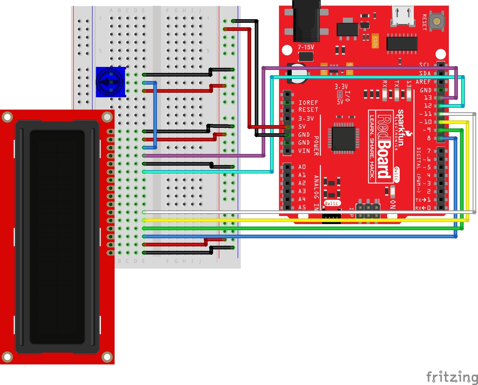
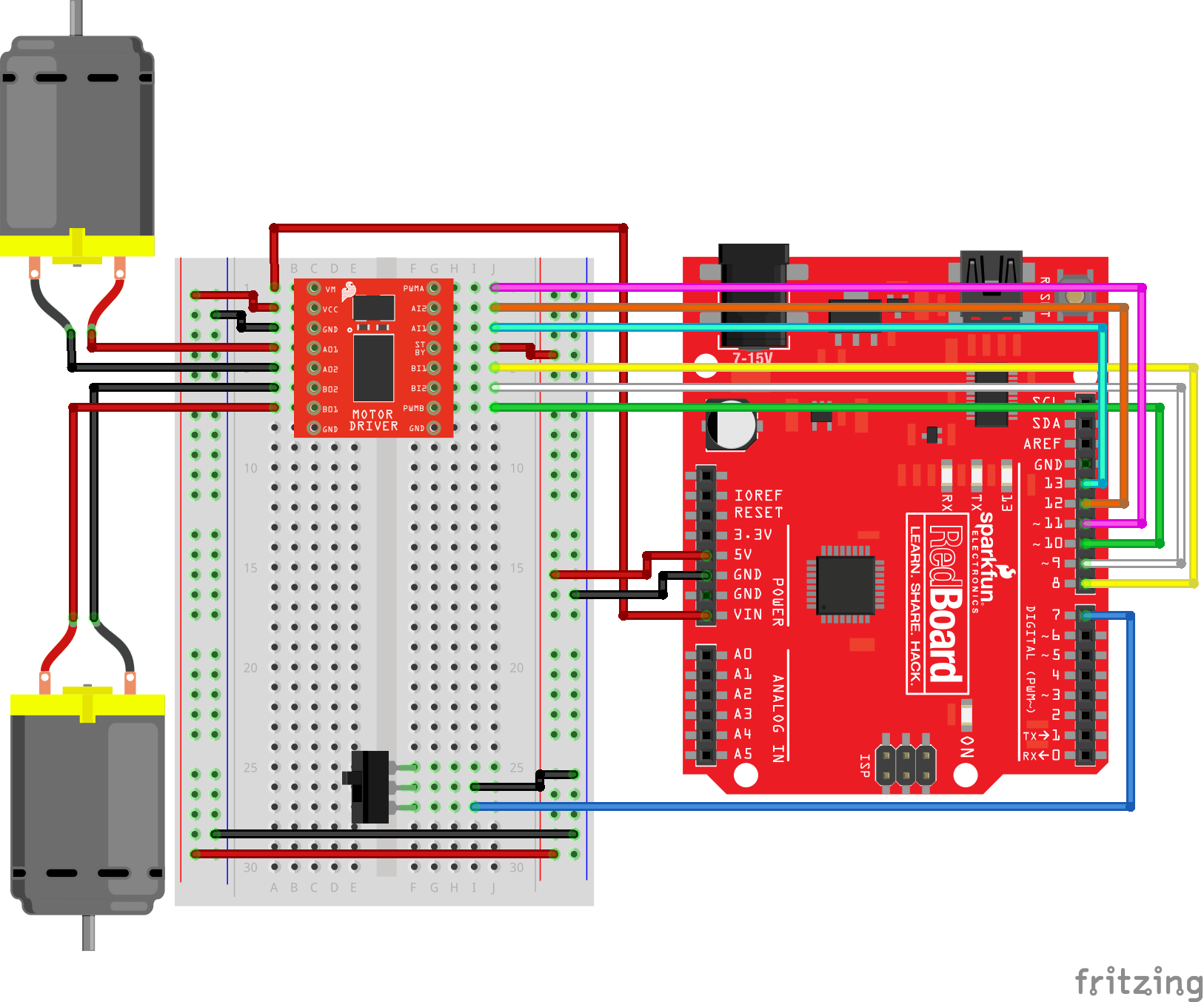
The correct circuit diagram for circuit 4A is as follows:
Corrections for V4.0 to V4.0a
Please Note: All of these corrections have been made to the online version of the SIK Guide. To follow along with the digital guide, click on the link below.
SparkFun Inventor's Kit Experiment Guide - v4.0
November 15, 2017
The SparkFun Inventor's Kit (SIK) Experiment Guide contains all of the information needed to build all five projects, encompassing 16 circuits, in the latest version of the kit, v4.0a.
To download a printable PDF of this Errata sheet, click the link below.
Page 73
The correct circuit diagram for circuit 4A is as follows:
Page 82
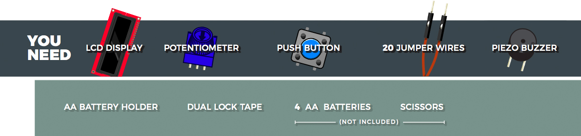
The You Need parts list is missing a Buzzer, which is needed to build circuit 4C. The correct parts list is shown below.
Page 84
The circuit diagram is correct, however the coordinates listed for the Buzzer and the Jumper Wires that connect the Buzzer to the RedBoard are incorrect. The correct coordinates are:
| Component | RedBoard | Breadboard | Breadboard |
|---|---|---|---|
| Buzzer | G6 (Buzzer +) |
G8 (Buzzer -) |
|
| Jumper Wire | Digital Pin 6 | J6 | |
| Jumper Wire | J8 | GND Rail ( - ) |
Page 93
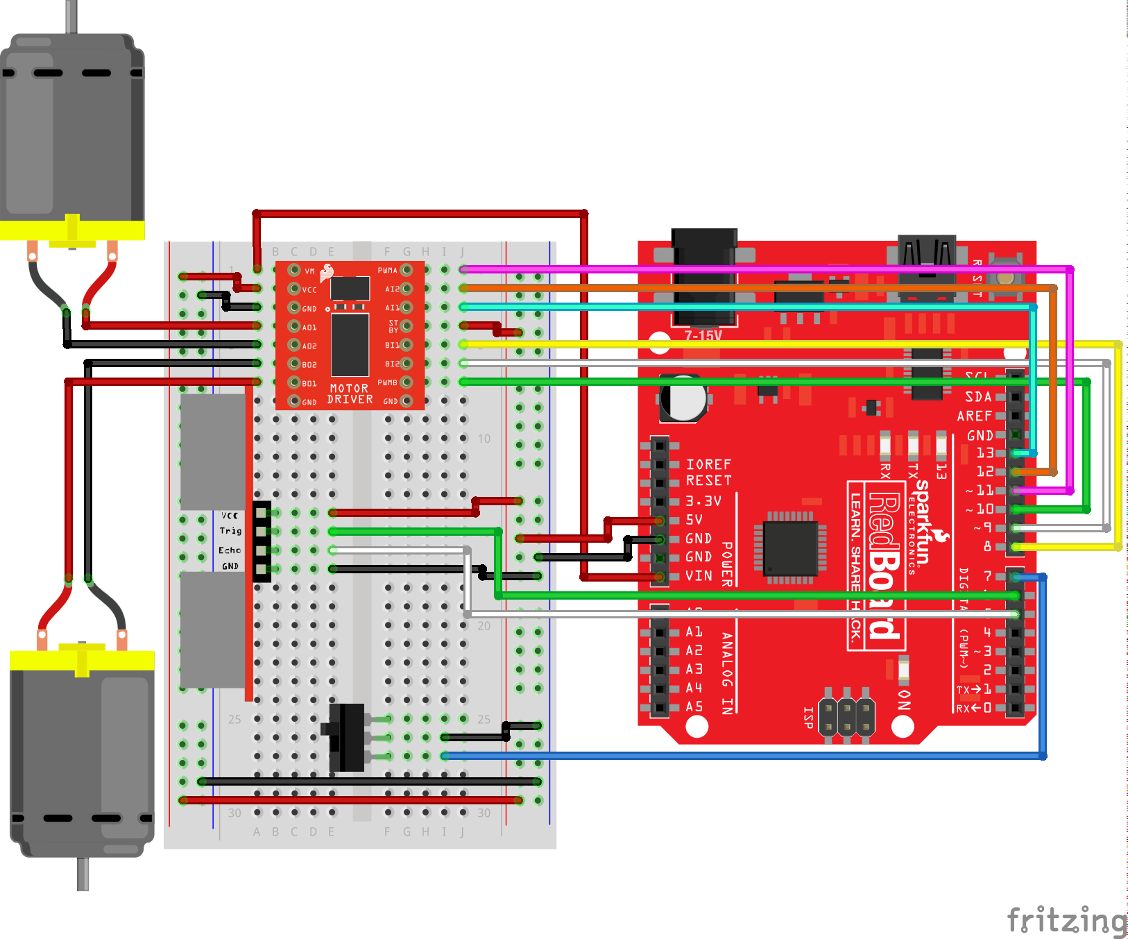
The correct circuit diagram for circuit 5A is as follows:
Changes made to the circuit diagram are also reflected in the hookup table revisions shown below.
| Component | RedBoard | Breadboard |
|---|---|---|
| Jumper Wire | Digital Pin 8 | J5 |
| Jumper Wire | Digital Pin 9 | J6 |
| Jumper Wire | Digital Pin 10 | J7 |
| Jumper Wire | Digital Pin 11 | J1 |
| Jumper Wire | Digital Pin 12 | J2 |
| Jumper Wire | Digital Pin 13 | J3 |
Please make sure that you are using the most up-to-date version of the SIK v4.0a code (SIK_Guide_Code-V_4.0a) with this diagram.
Page 98
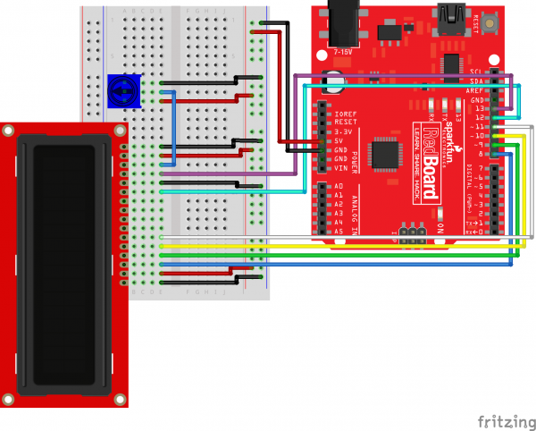
The correct circuit diagram for circuit 5B is as follows:
Changes made to the circuit diagram are also reflected in the hookup table revisions shown below.
| Component | RedBoard | Breadboard |
|---|---|---|
| Jumper Wire | Digital Pin 8 | J5 |
| Jumper Wire | Digital Pin 9 | J6 |
| Jumper Wire | Digital Pin 10 | J7 |
| Jumper Wire | Digital Pin 11 | J1 |
| Jumper Wire | Digital Pin 12 | J2 |
| Jumper Wire | Digital Pin 13 | J3 |
Please make sure that you are using the most up-to-date version of the SIK v4.0a code (SIK_Guide_Code-V_4.0a) with this diagram.
Page 103
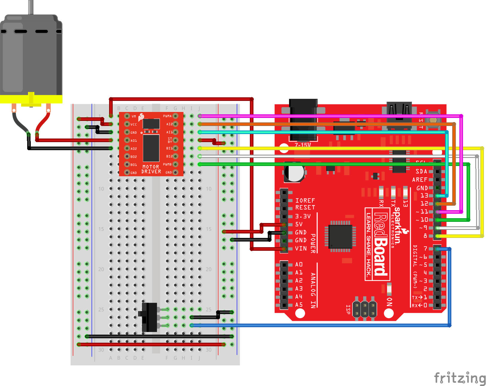
The correct circuit diagram for circuit 5C is as follows:
Changes made to the circuit diagram are also reflected in the hookup table revisions shown below.
| Component | RedBoard | Breadboard |
|---|---|---|
| Jumper Wire | Digital Pin 8 | J5 |
| Jumper Wire | Digital Pin 9 | J6 |
| Jumper Wire | Digital Pin 10 | J7 |
| Jumper Wire | Digital Pin 11 | J1 |
| Jumper Wire | Digital Pin 12 | J2 |
| Jumper Wire | Digital Pin 13 | J3 |
Please make sure that you are using the most up-to-date version of the SIK v4.0a code (SIK_Guide_Code-V_4.0a) with this diagram.
SIK Code
The changes made to Project 5's circuit diagrams also necessitate a change to the code for each circuit. Please make sure you are using the most up-to-date SIK code, which can be downloaded using the button below or at the following URL: www.sparkfun.com/SIKcode