ADXL337 and ADXL377 Accelerometer Hookup Guide
 JordanDee
Hardware Overview
The Breakout Boards for the ADXL337 and ADXL377 break out the all the pins you'll need to get the necessary data from the accelerometers.
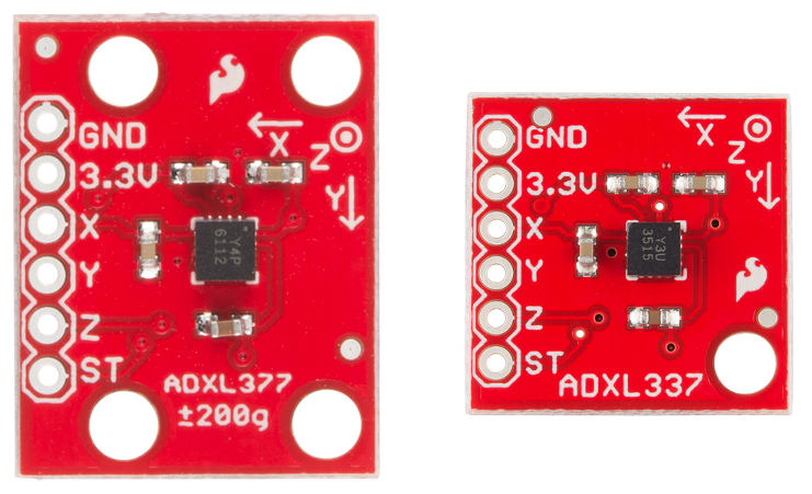
As you can see, each breakout has the same pins broken out. Here is some information about each pin:
| Pin Label | Pin Function | Input/Output | Notes |
|---|---|---|---|
| 3.3V | Power Supply | Input | Can be between 1.8 - 3.6V. |
| X | X axis acceleration | Output | Analog output whose voltage correlates to acceleration measured on the X axis |
| Y | Y axis acceleration | Output | Analog output whose voltage correlates to acceleration measured on the Y axis |
| Z | Z axis acceleration | Output | Analog output whose voltage correlates to acceleration measured on the Z axis |
| ST | Self Test | Input | Used to verify sensor functionality |
| GND | Ground | Input | 0V, common voltage to share with microcontroller circuit |
Voltage Supply Requirements
The big alert here is that the ADXL337 and ADXL377 both have a maximum voltage of 3.6V -- that range applies to both the power supply and the self test pin. You can use a 5V or 3.3V micro with these sensors as long as you power the board with 3.3V. Be aware though, that your analog to digital (ADC) readings will vary depending on whether you're using a 5V or 3.3V micro! Both will work, just be aware of how it affects the numeric values the microcontroller reads.
Fortunately, you don't need a lot of power to make the accelerometers work. In normal operating mode they typically draw about 300µA.
Extra Hardware Notes
If you are powering either the ADXL337 or ADXL377 with 3.3V, a voltage reading of 1.65V on the X pin will correspond to an acceleration reading of 0g for both chips. However, if the X pin reads 3.3V, on the ADXL337 this means a force of 3g is being applied on the x axis while the same reading on an ADXL377 would indicated a force of 200g. The usage of both chips is essentially the same, but interpreting the readings is different due to the scale that each chip measures.
The ADXL377 also has 4 mounting holes, as opposed to just two, to allow for a more secure physical connection to your project since it will likely be subjected to more extreme force.
Also, for both chips, 0.01µF capacitors are used on the X, Y, and Z outputs. This means the maximum rate you can collect acceleration data from the IC's is 500Hz.