Are You Okay? Widget
Contributors:
elecia
Building The Hardware
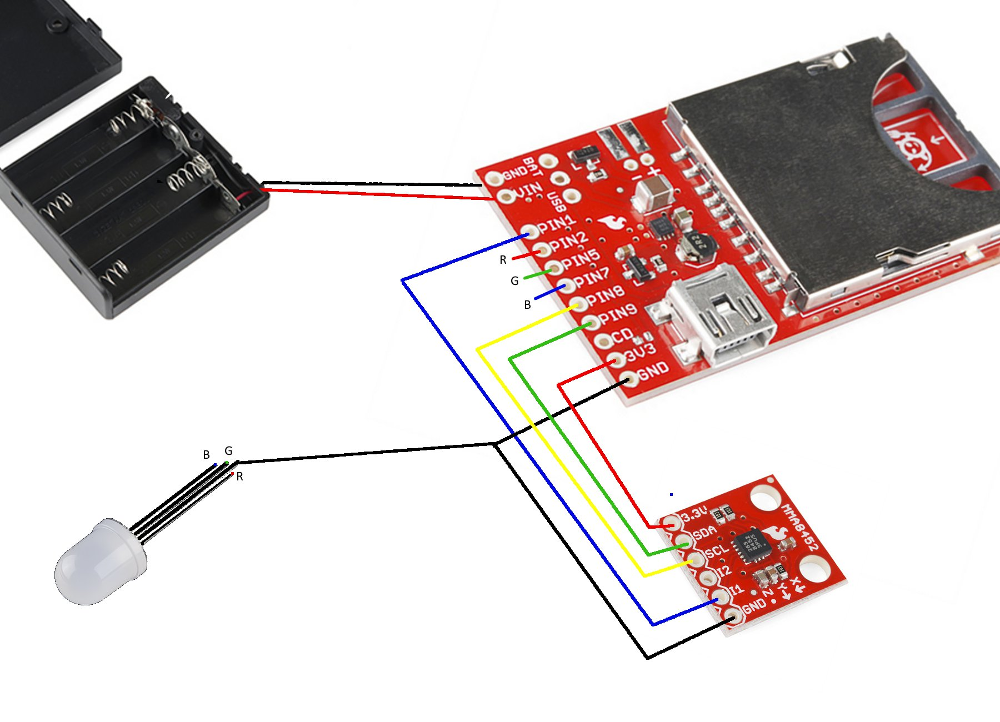
Here's an overview of the hardware hookup:
The build is fairly straight forward. We start with soldering:
- Attach a two pin header to the Electric Imp breakout board for GND and VIN. Solder on the battery wires. Hot glue them to reinforce the connection.
- Break off 9 pins from the header, and solder those to the Imp breakout board.
- Since you’ll need two ground wires (one for the accelerometer and one for the LED), cut the end off of one jumper wire, strip the coating, and solder it to the Imp breakout board. (We can wait to hot glue until the jumper wires are in place.)
- Solder a 6-pin header onto the accelerometer.
Now wire up the system:
| Imp Breakout Pin | Wire Color | Goes To | Use |
|---|---|---|---|
| PIN1 | Blue | Accel's I1 | Interrupt to wake up the Imp. |
| PIN2 | Red | LED's red leg | PWM red |
| PIN5 | Blue | LED's blue leg | PWM blue |
| PIN7 | Green | LED's green leg | PWM green |
| PIN8 | Yellow | Accel's SCL | I2C clock signal |
| PIN9 | Green | Accel's SDA | I2C data signal |
| 3V3 | Red | Accel's 3.3V | Power |
| GND | Black | Accel's GND | Ground |
| GND | Black | LED cathode (longest leg) | Ground |
After you are done, the result should look something like this:
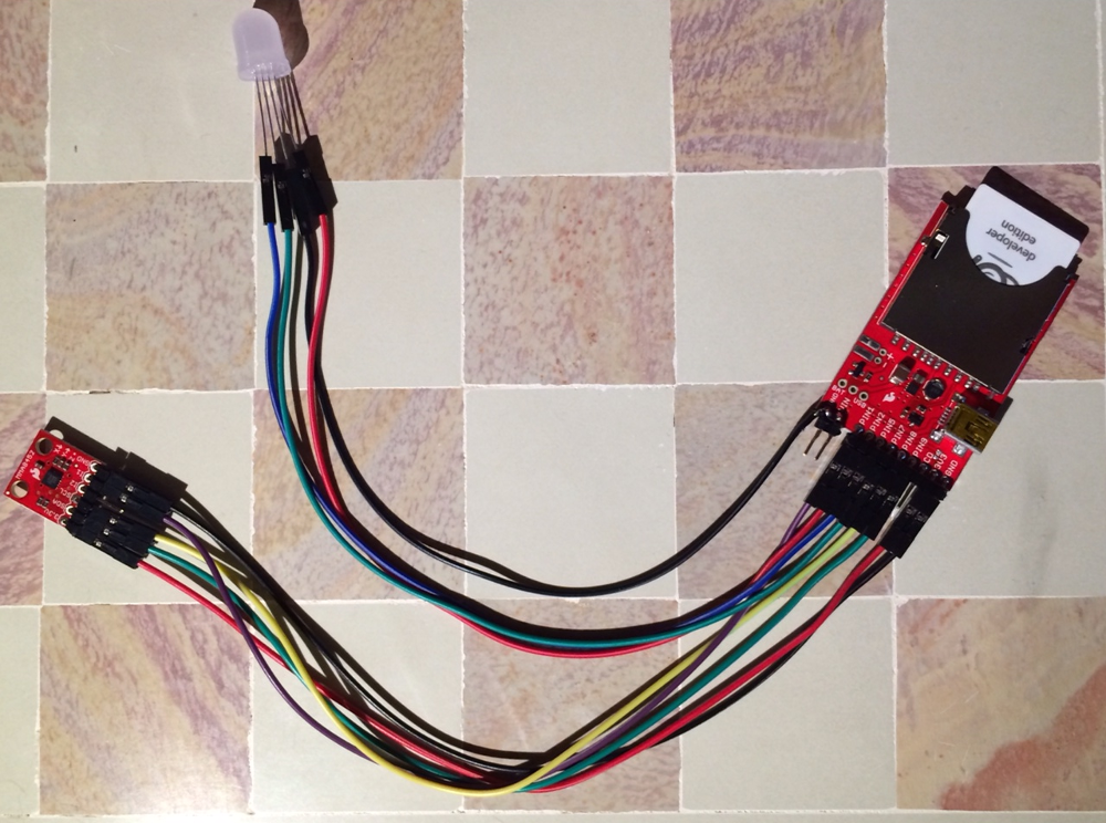
Note: the extra ground wire is soldered on the 2-pin power header and is ready for a battery connection to be soldered to it.