AST-CAN485 WiFi Shield Hookup Guide
 Alex the Giant, Ell C, JamesBM
Hardware Overview
Input Power
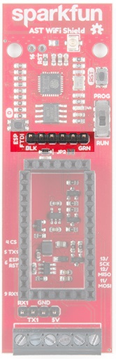
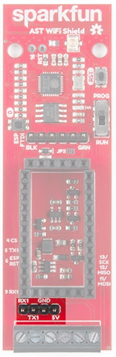
The AST-CAN485 WiFi Shield provides screw terminals for your power, RS-485 signals, and CAN bus signals, presoldered to the board for fast and secure connections.
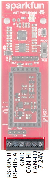
The input voltage range is 7-24VDC. The input voltage is regulated down to 5V to supply power the CAN485 board, as well as 3.3V to power the ESP8266.
ESP8266
Based on the SparkFun ESP8266 Thing, you can use either the PCB trace antenna, or the U.FL connector if housed in a metal enclosure.
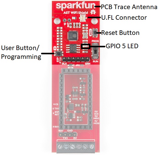
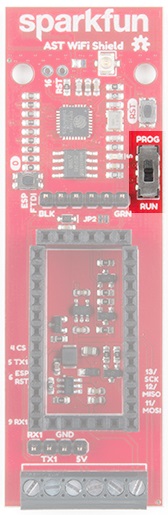
Programming Switch
Because the UARTs are connected together for the CAN485 board and the ESP8266, a switch is used to separate the RX and TX signals. When programing either the ESP8266 or CAN485 board, move the switch over to the PROG position, and after the upload is complete, toggle the switch to the RUN position.
Speaking of programming, the ESP8266 runs off of 3.3V logic, so to program the ESP8266, a 3.3V USB to UART bridge is used.
AST-CAN485 Serial Port
A header breaks out the Software Serial port used by the CAN485. This can be used as a debugging serial port or to connect other devices.
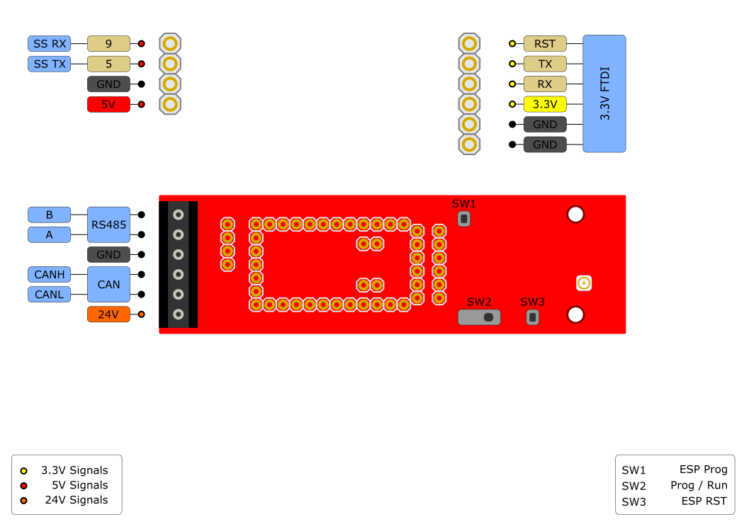
Pinouts
The pinout for the WiFi Shield is shown below:
Schematic
The schematic below shows the layout of the interconnects between an inserted CAN485 module and the integrated ESP module.
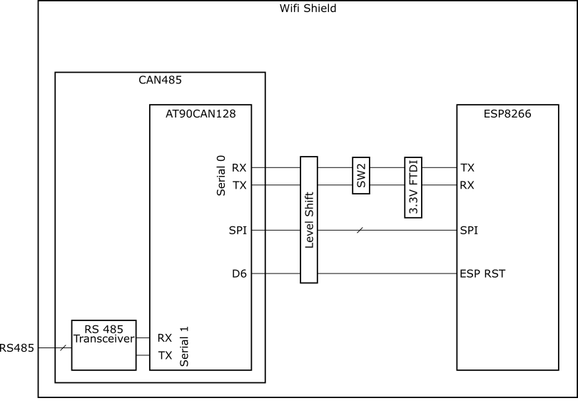
The primary interface between the CAN485 and the ESP8266 is a serial port. It operates on hardware serial port 0 on the CAN485 rather than the traditional Software Serial port. The reason for this is that it enables higher speed communications between the two devices. The trade-off of this feature is that it uses the main serial port, which is also used to program the CAN485 and is broken out on its FTDI header. This means that in order to program the CAN485 module, while it is inserted, the serial port must be disconnected. For this reason, the mode selection switch was added which allows for the rx and tx lines to be disconnected. In a similar way, the same serial port is used to both program the ESP8266 and communicate with the CAN485. The mode selection switch also enables the ESP to be programmed by disconnecting it from the CAN485.