Bi-Directional Logic Level Converter Hookup Guide
 jimblom
Board Overview
If you take a peek at the board's schematic, you'd find that the bi-directional logic level converter (let's shorten that to BD-LLC) is actually a very simple device. There is basically one level-shifting circuit on the board, which is repeated four times to create four level-shifting channels. The circuit uses a single N-channel MOSFET and a couple pull-up resistors to realize bi-directional level shifting.
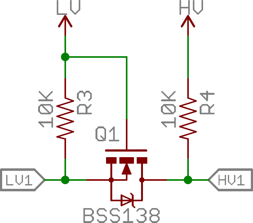
Through some semiconductor magic, this circuit can shift a low voltage signal to high and/or shift a high-voltage signal to a low voltage. A 0V signal on one end remains a 0V signal on the other. For a complete analysis of this circuit, check out this excellent Philips Application Note AN97055.
The Pinout
There are 12 total pins on the BD-LLC -- two parallel rows of six headers. One row contains all of the high voltage (e.g. 5V) inputs and outputs, the other row has all things low voltage (e.g. 3.3V).
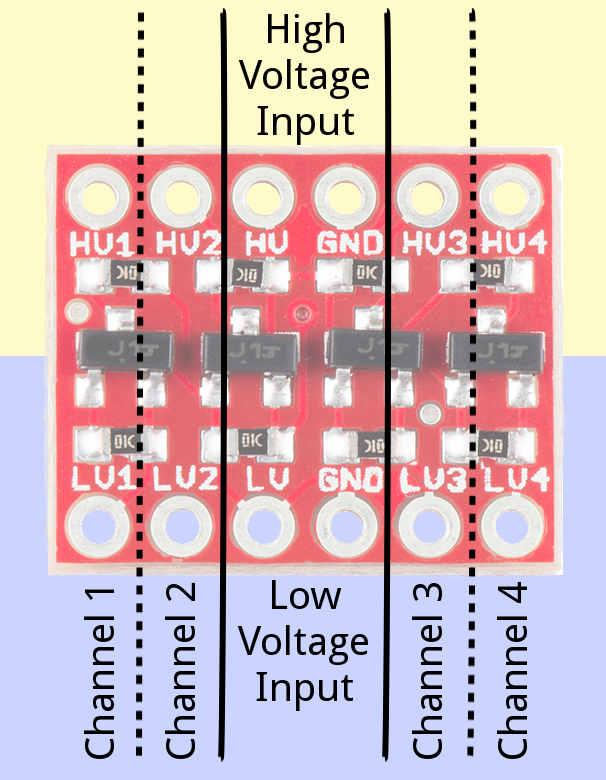
The pins are labeled on both the bottom and top sides of the board, and organized into groups. Let's look closer at some of the pin groups:
Voltage Inputs
The pins labeled HV, LV, and two GND's provide high and low voltage references to the board. Supplying a steady, regulated voltage to both of these inputs is required.
The voltage supplied to the HV and GND inputs should be higher than that supplied to the LV side. For example, if you're interfacing from 5V to 3.3V, the voltage on the HV pin should be 5V, and the voltage on LV sould be 3.3V.
Data Channels
There are four separate data channels on the BD-LLC, each capable of shifting data to and from high and low voltages. These pins are labeled HV1, LV1, HV2, LV2, HV3, LV3, HV4, and LV4. The number at the end of each label designates the channel of the pin, and the HV or LV prefix determines whether it's on the high or low side of the channel.
A low-voltage signal sent in to LV1, for example, will be shifted up to the higher voltage and sent out HV1. Something sent in HV3 will be shifted down and sent out of LV3. Use as many of these channels as your project requires. You don't have to use every single one.
Keep in mind that these level shifters are purely digital. They can't map an analog voltage from one max voltage to another.