Buck-Boost Hookup Guide
 Alex the Giant, Ell C
Buck-Boost Tips and Tricks
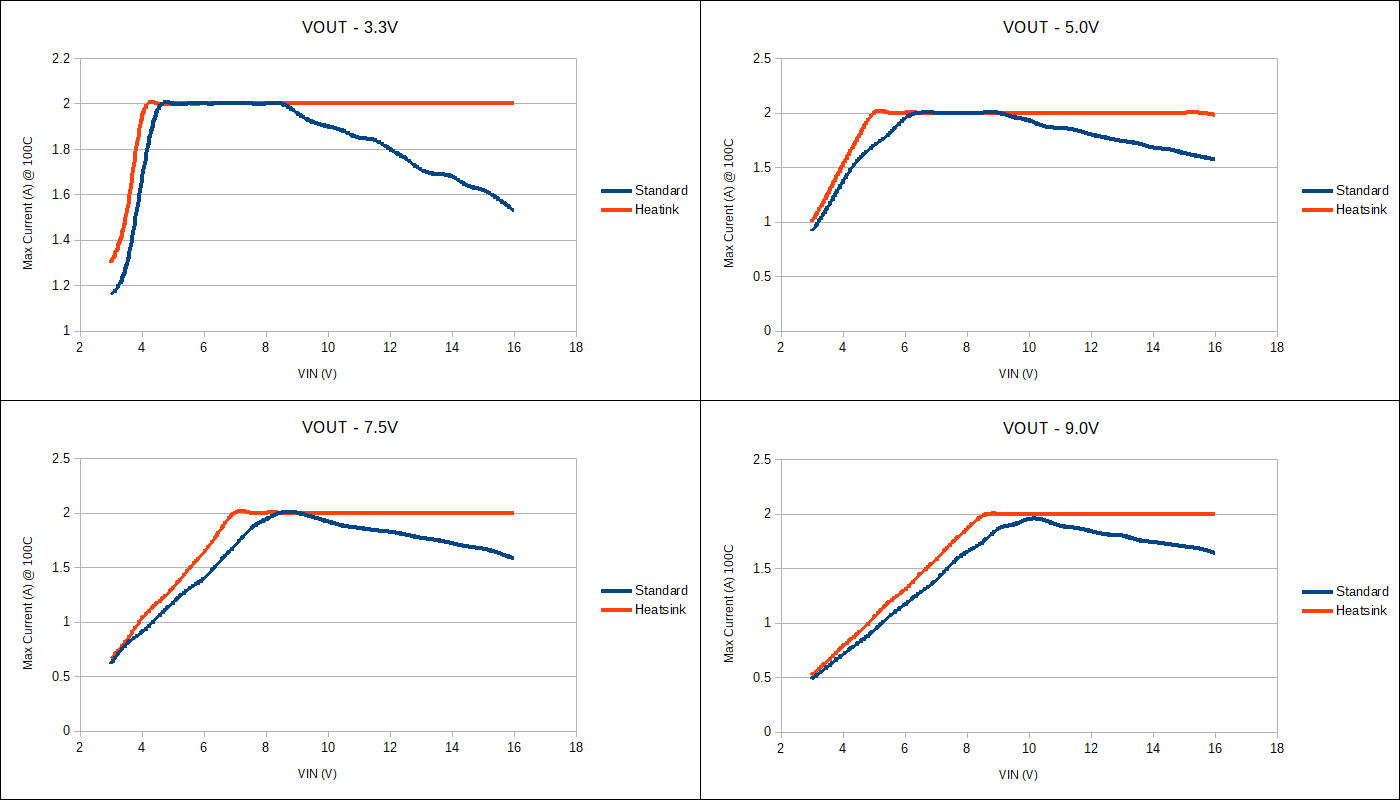
Maximum Output Current VS Input Voltage
One of the benefits of the Buck-Boost, aside from boosting the output voltage up from a lower input voltage, is it uses a switching DC/DC converter, which is more efficient than a linear regulator. More efficiency means less energy is wasted in the form of heat. However, that doesn't mean the TPS63070 doesn't get hot under load. The TPS63070 has an operating die temperature range of -40 to +125°C, using the graphs below should provide a good rule of thumb for the maximum output current available at various output voltages as a function of the input voltage.
The temperature was recorded using a FLIR camera with an air temperature of 25°C, with a maximum case temperature of 100°C. Each output voltage graph has a showing the maximum output current both with and without a heatsink.
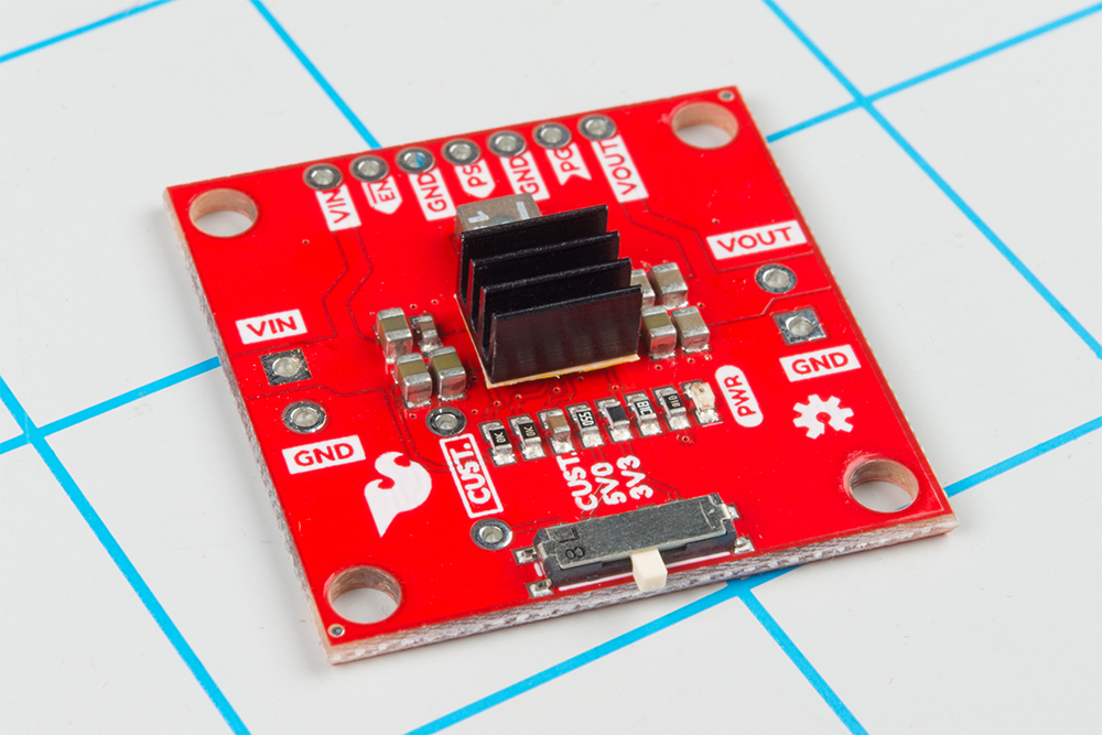
Adding a Heatsink
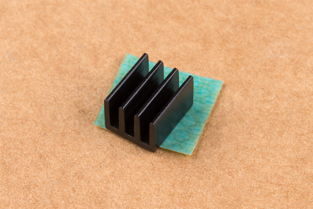
In the maximum output current section, the graphs are shown both with and without a heatsink. The benefit of a heatsink is it provides more surface area for the air to dissipate the heat, which will allow the Buck-Boost board to output the maximum amount of current across a wider input voltage range. To add a heatsink you'll need two of our products: a heatsink (of course), and our thermal tape.
To add a heatsink first cut the thermal tape to rough size:
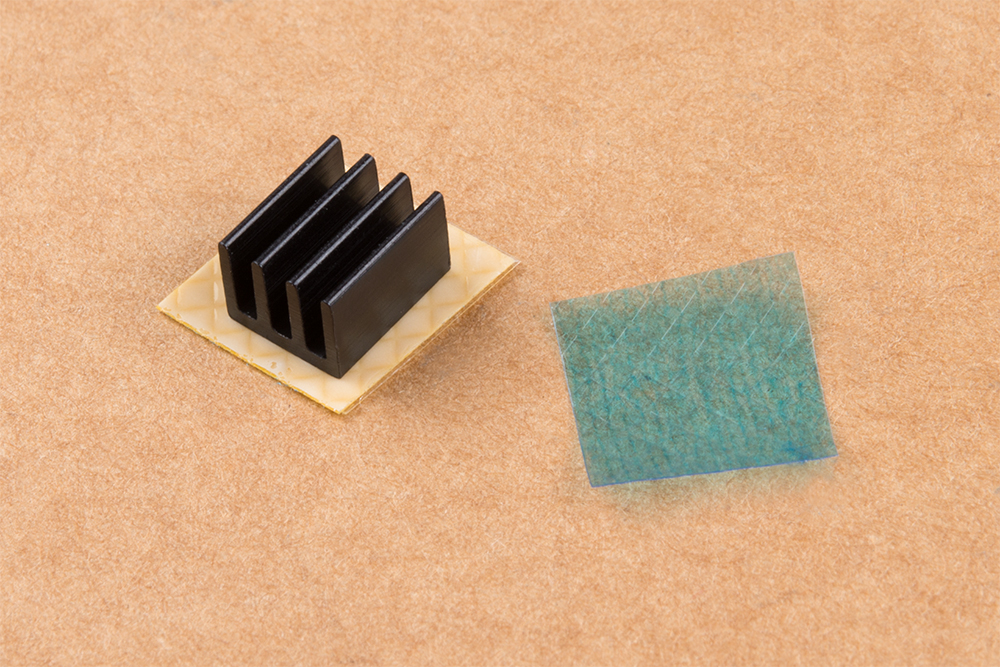
Peel off one of the protective coverings and attach heatsink to thermal tape:
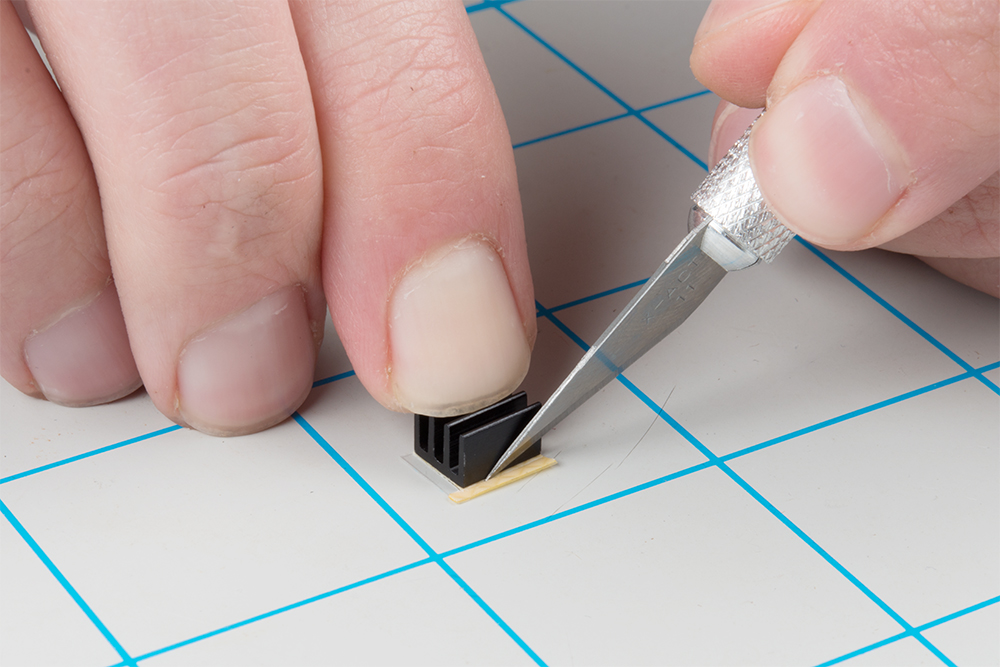
With a hobby knife, follow the perimeter of the heatsink to cut the tape to it's final size:
Remove the remaining protective covering of the tape and attach the heatsink to the TPS63070, trying to center the heatsink over the IC:
Connecting your Load
Depending on the size of the load connected to the output, you may need to wait between when the enable pin is pulled high and the load is connected to the board. The time delay is relatively short (~10ms), but it shouldn't be a problem if the load is <800mA at 3.3V, or <700mA at 5.0V. If the custom resistor is populated to output a voltage greater than 5V, you should be able to leave the load connected if the load is <650mA.