Interactive LED Music Visualizer
 Michael Bartlett
Assembly
Depending on your setup, the project may not require any soldering! The few exceptions will probably be soldering some pins to the sound detector, and, if you've cut a roll of addressable LEDs in the middle, you'll have to solder some wires to the starting LED's pins. If you've never soldered before, I highly suggest taking a look at this guide to solder.
Below is also a general chart for how the pin(s) on each component should be routed and an accompanying diagram. Before you begin, here are some things to keep in mind:
- Be conscious of the orientation you think would allow the sound detector to take optimal readings for your intentions. Bending the pins to hold the sound detector perpendicular to the breadboard is a recommended option.
- Electrolytic capacitors are polarized, so how they are oriented is important. Make sure to place the side with a white stripe and a negative symbol into a negative current (ground) and the other into positive current.
- Resistors and pushbuttons are not polarized.
- Trimpots are not polarized either, however their middle pin is the analog output, so don't power that directly.
The pins used in the diagram and the code are in parentheses. If you use a different pin, don't forget to change it in the code as well:
| Sound Detector | Addressable LED strip | Trimpot | Pushbutton | 1 mF (1000 µF) Capacitor | 300–500 Ω Resistor |
|---|---|---|---|---|---|
| Envelope → Analog (A0) | Digital/Analog (A5) → Resistor → DIN | 5V → left or right pin | GND → Either side | Between ground and 5V | Between Digital/Analog (A5) and DIN on LED strip |
| 3.3V → VCC | 5V →5V | Middle pin → Analog (A1) | Other side → Digital (4, 5, 6) | ||
| GND → GND | Remaining left or right pin → GND |
The circuit should look something like the diagrams below. If you just want the LEDs to react to sound using one visualizer and one color palette, you can build the simple circuit on the left. If you want to take advantage of all the visuals, palettes, and shuffle mode, you can build the full circuit on the right.
 |
 |
| Simple Circuit | Full Circuit |
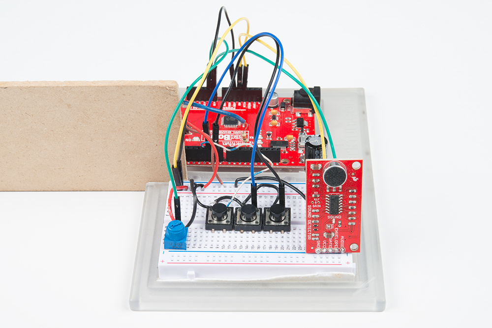
After assembling the circuit, you should have something similar to the image below. Depending on your setup, you may have less components.