LTE GNSS Breakout - SARA-R5 Hookup Guide
 El Duderino,
  PaulZC
Hardware Assembly
In this section we'll go over the basics of connecting the LTE GNSS Breakout to your computer along with some tips on how to use it in some alternate configurations.
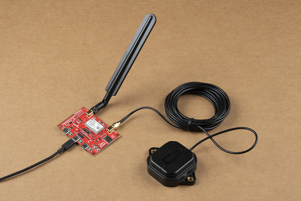
Basic Assembly
For quick basic assembly, connect the LTE and GNSS antennas to their respective SMA connectors and then plug in the board to your computer with a USB-C cable connected to the UART1 USB-C connector.
Your computer should automatically install any necessary USB drivers for the breakout when it is plugged in for the first time. In case your computer does not automatically install the USB drivers for the CH340 serial converter IC, read through our How to Install CH340 Drivers tutorial:
Dual UART Configuration
As covered in the Hardware Overview section, the LTE GNSS Breakout comes pre-configured for single UART behavior. In order to use one of the dual UART variants, make the following modifications to the board:
- Open the DTR, DCD, RI and DSR jumpers.
- Close the UART2 jumpers labeled TXD2, RXD2, RTS2 and CTS2
- Adjust the IN/OUT jumper from the "OUT" (default) position to the "IN" position.

Use the +USIO AT Command to select which variant you prefer. Refer to section 15.8 of the AT Command Set Manual for more information on the configuration selection command and section 1.9.1 of the System Integration Manual for detailed descriptions of the UART interface variants.
Arduino Assembly
Users who wish to use the LTE GNSS Breakout with an Arduino microcontroller need to solder to the board. If you are not familiar with through-hole soldering or want a refresher, take a look at this tutorial:
How to Solder: Through-Hole Soldering
September 19, 2013
Before soldering to the breakout, make the following adjustments to use the board with the u-blox SARA-R5 Arduino Library:
- Open the TXD_I, RXD_O, RTS_I and DTR/TXD2_I Solder Jumpers.
- Solder either headers or wire to the TXD I and RXD O PTH pins.
- Power the circuit using one of the following options:
- If powering the LTE GNSS Breakout from the Arduino, solder headers or wire to V_EXT PTH pin and one of the Ground PTHs.
- If powering the LTE GNSS Breakout and Arduino via the same power source (e.g. USB on the same computer), no power connections are necessary.
- If separate power supplies are used for both boards, make sure to create a common ground between the two circuits.
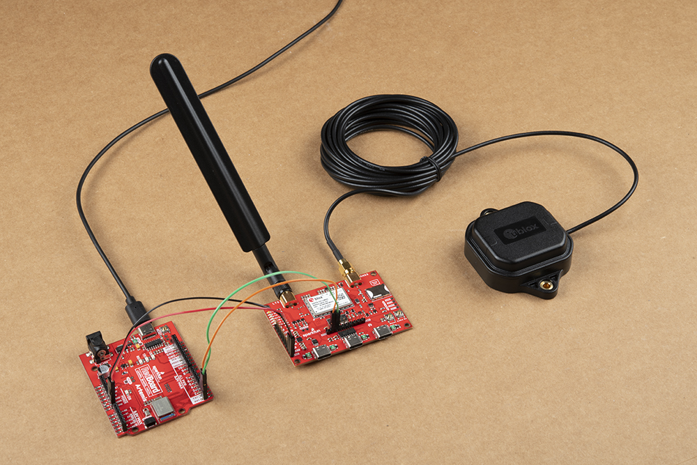
With the board modified, make the appropriate connections between the LTE GNSS Breakout and Arduino. The connections listed below assume the RedBoard/Arduino provides power to the LTE GNSS Breakout at 5V via USB:
- LTE GNSS TXD I → RedBoard TX1 (if using Serial1) or D9 (if using SoftwareSerial)
- LTE GNSS RXD O → RedBoard RX1 (if using Serial1) or D8 (if using SoftwareSerial)
- LTE GNSS V_EXT → RedBoard VIN
- LTE GNSS GND → RedBoard GND
This tutorial uses a SparkFun RedBoard Artemis for the Arduino examples so the completed circuit looks like the photo below: