MyoWare Muscle Sensor Kit
 .Brent.
 Putting it All Together
As mentioned above, there are two ways to attach the sensor pads to a user. They can be attached directly to the sensor board, or to the the end of a cable via the MyoWare Cable Shield.
In the image below, the left most electrode connection should be connected to the end of a muscle group being measured. Again, the cable color codes can vary depending on the manufacture. Relative to the current MyoWare Shield and the electrode cable that is sold in SparkFun's catalog, this is equivalent to using the blue insulated conductor connected to the pin labeled E. The mid muscle electrode on the right breaks out on the red snap on the cable connected to the pin labeled M. The reference electrode has continuity with the black snap connected to the pin labeled R.
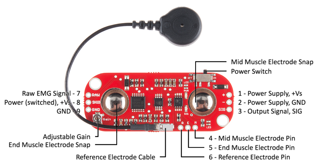
As shown in the image above, there are three rows of three 0.1" spaced plated through holes. On the right is the power supply +Vs, & ground, along with the processed output signal (holes 1, 2, & 3).
Along the long edge near the mid muscle electrode snap are the thru-holes for remote electrode connection (holes 4, 5, & 6).
On the opposite end are three 'outputs'. Hole 7 is the raw, unprocessed EMG signal. Hole 8 is the switched power. Power goes into the board via hole 1, is switched, and comes back out hole 8 ( if you believe in passive sign convention (PSC) ). Hole 9 is the ground reference for the switched power.
The shields come with assorted support for these pins. Some shields such as the Power Shield don't support the remote connections. If you need access to these pins the boards that use or can pass them through must go lower in the stack. Both the Cable Shield and the Proto Shield have this connection capability.
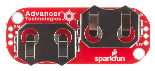
MyoWare Power Shield (top view)
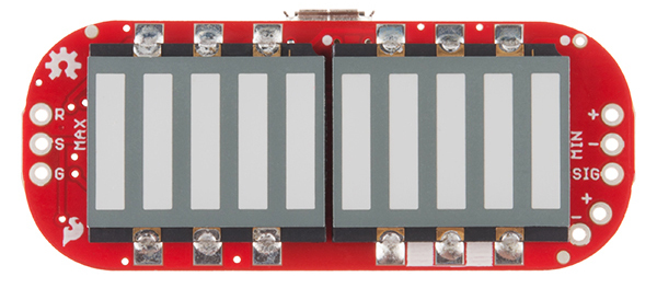
MyoWare LED Shield (top view)
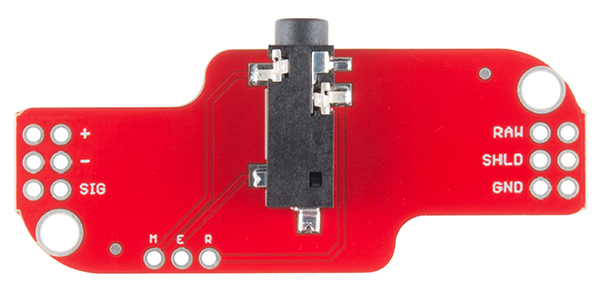
MyoWare Cable Shield (bottom view)
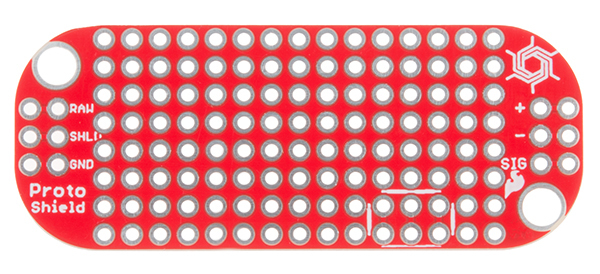
MyoWare Proto Shield (top view)
Take note of the second row of holes on the Cable and Proto shields. This allows for stacking multiple shields using standard 0.1" headers or the stackable variety.


Option 1
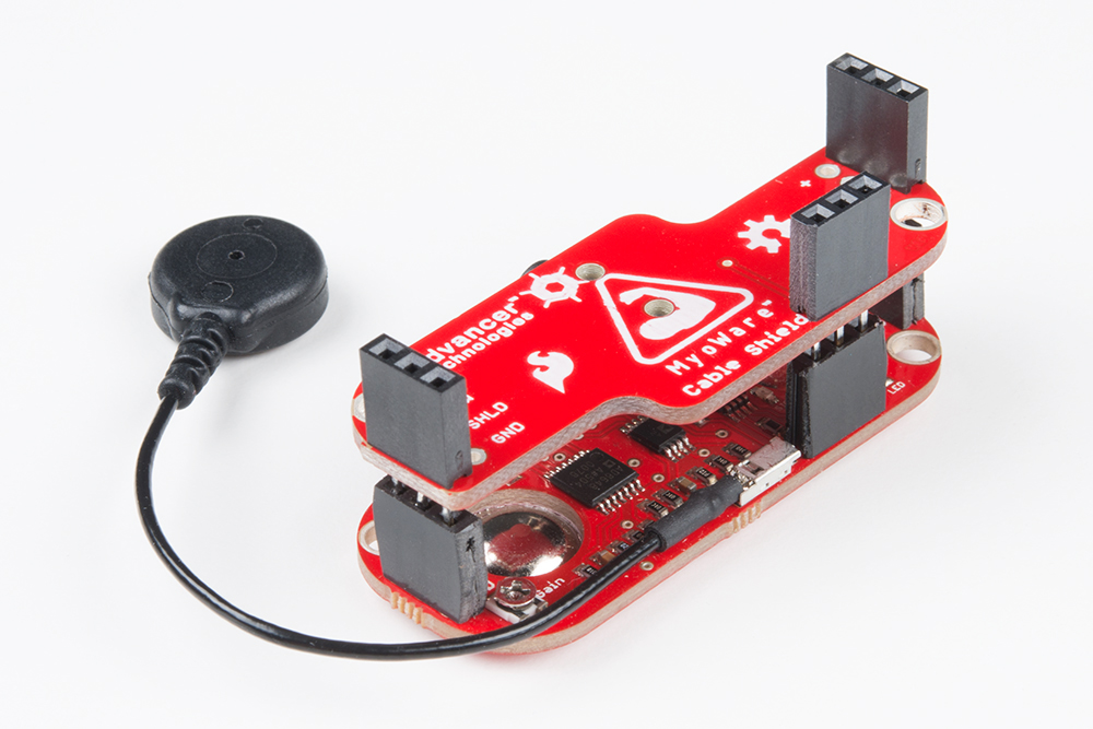
The headers listed provides the user with a few options to stack the shields together. We found it easier to have the MyoWare sensor and shields populated with female headers. If using the stackable headers supplied with the kit, it is likely that you will want to flush cut the long leads from the bottom using diagonal cutters. Below is an example of the cable shield stacked on the MyoWare sensor.

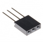
3-Pin Stackable Header
Option 2
It's also possible to have a setup where you might want use male header pins in the stack. If using the parts provided in the kit, these male headers will likely be populated on the bottom stack. The bottom board should in most cases have male headers populated on the outer bottom rows to mate with the boards that will be stacked on top. The board to be stacked on top should have female headers facing the male header pins.