PiRetrocade Assembly Guide
 LightningHawk
Kit Assembly
For step-by-step instructions on how to assemble the PiRetrocade, watch the video below. Then read on for more detailed instructions.
Hardware
This project really boils down to five buttons and a joy stick connected to the GPIO pins on the Raspberry Pi 3 and an SD card fully loaded with arcade software. Let's get started building this controller. Insert the SD Card into the Raspberry Pi . On top of the box, you will find blue prints for your controller layout. Use the provided hobby knife to cut holes labeled "Cut".
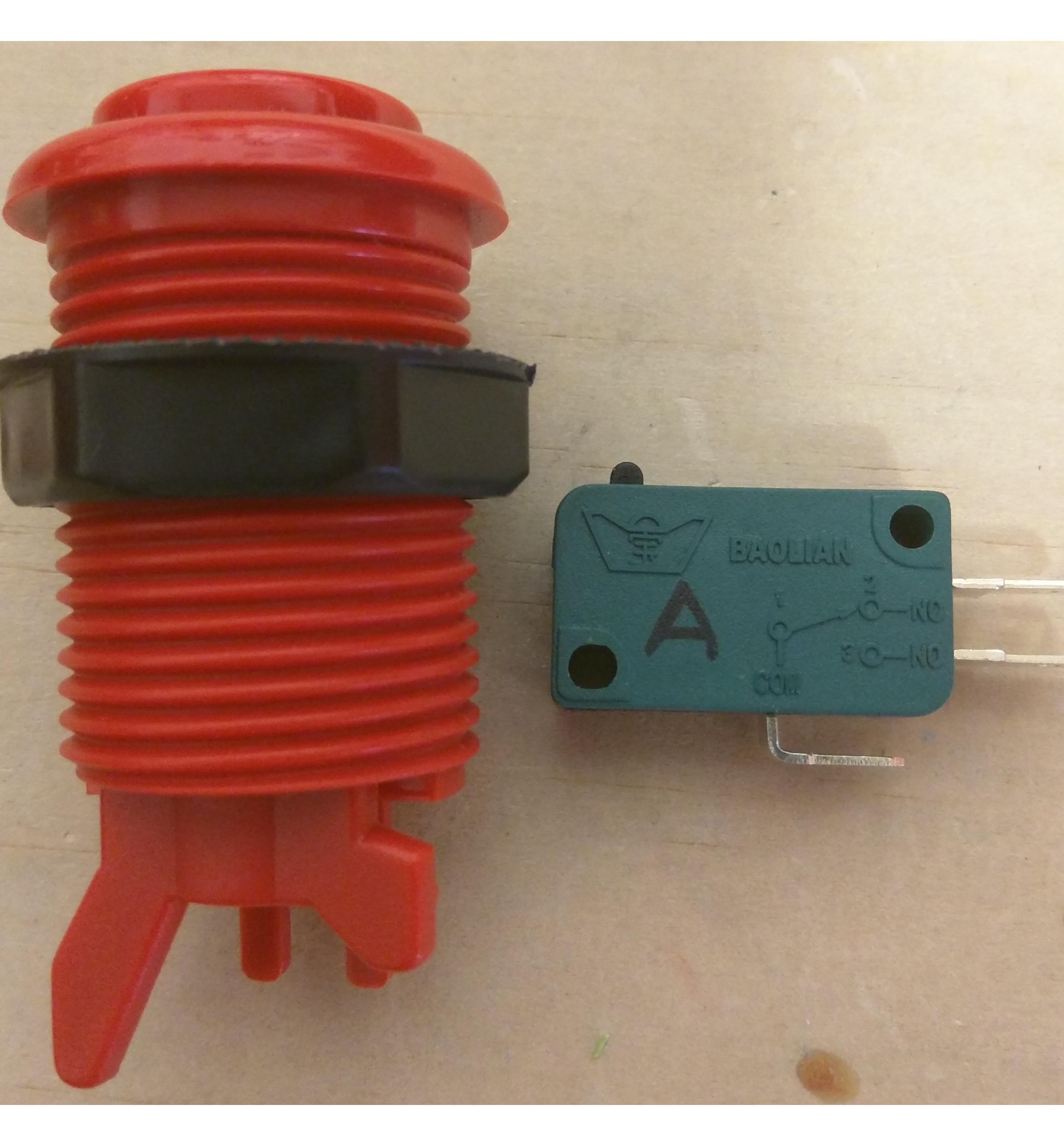
Buttons
Remove the switches from the arcade buttons. Unscrew the nut, and feed a button through each hole and secure the button to the box with the nut. Once they are all in place, replace the switches.

Joystick
First, figure out which switch corresponds to Up, Down, Left and Right. To do this easily, you can unscrew the bottom metal plate like this:
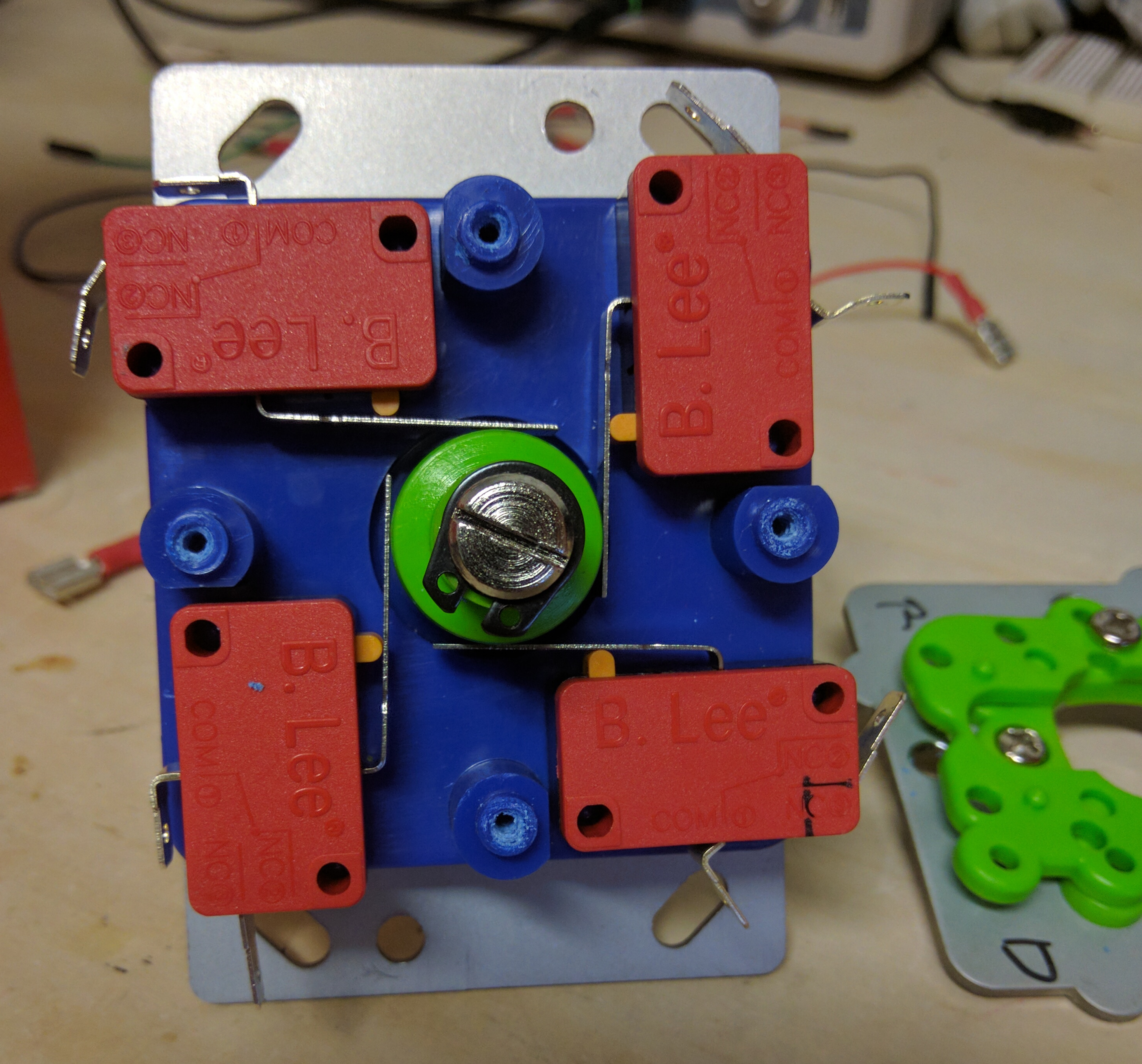
The switches will be exposed and you can test each direction. With the orientation shown holding the joystick to the left produces this result:
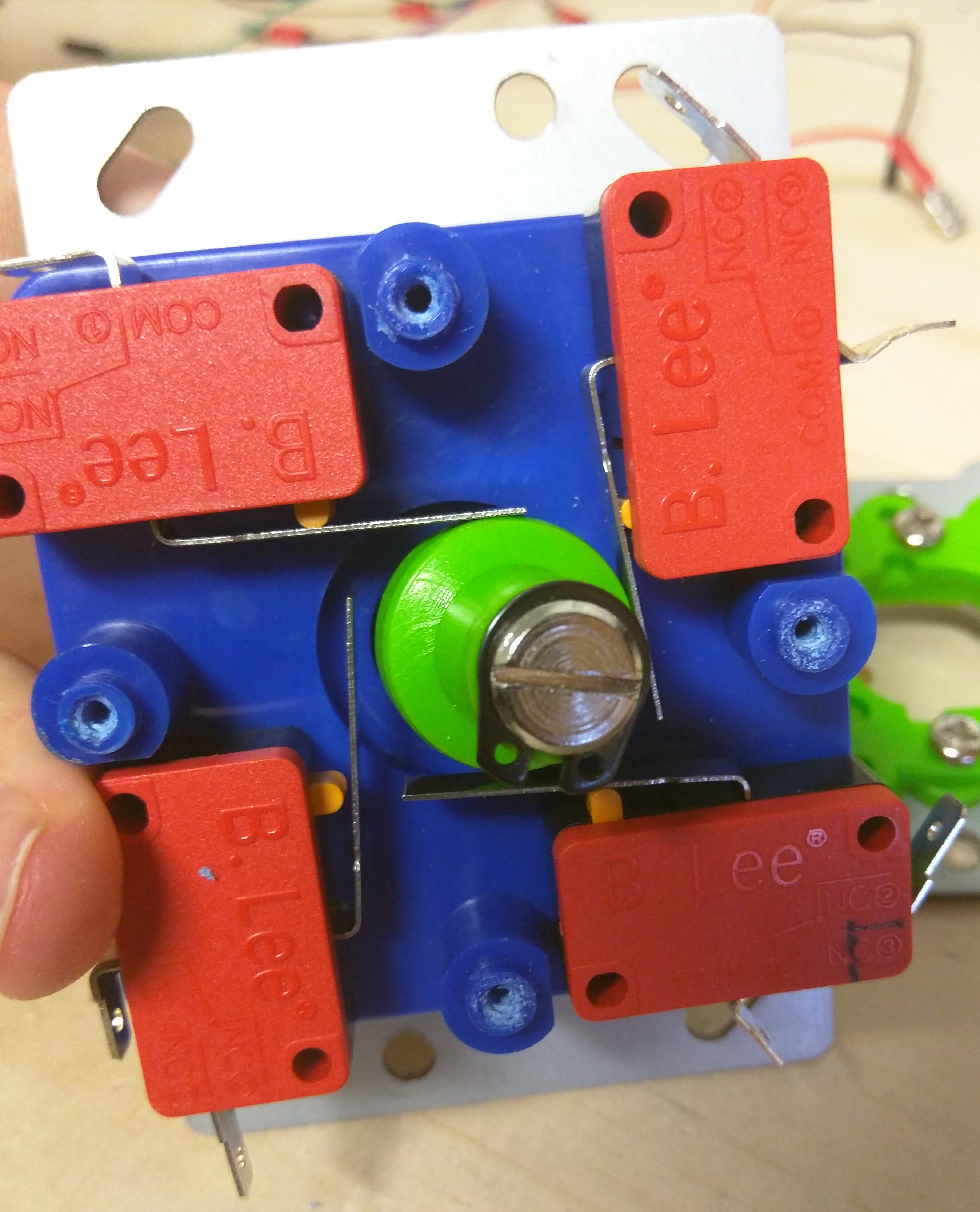
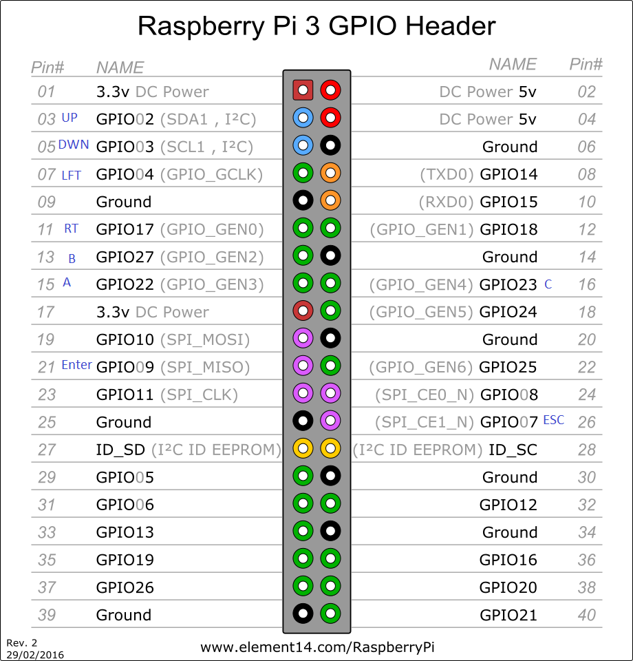
I labeled that top right switch "Left" which corresponds to GPIO Pin 7. Continue the same process for each direction and replace the bottom cover with the four screws along the outer edge.
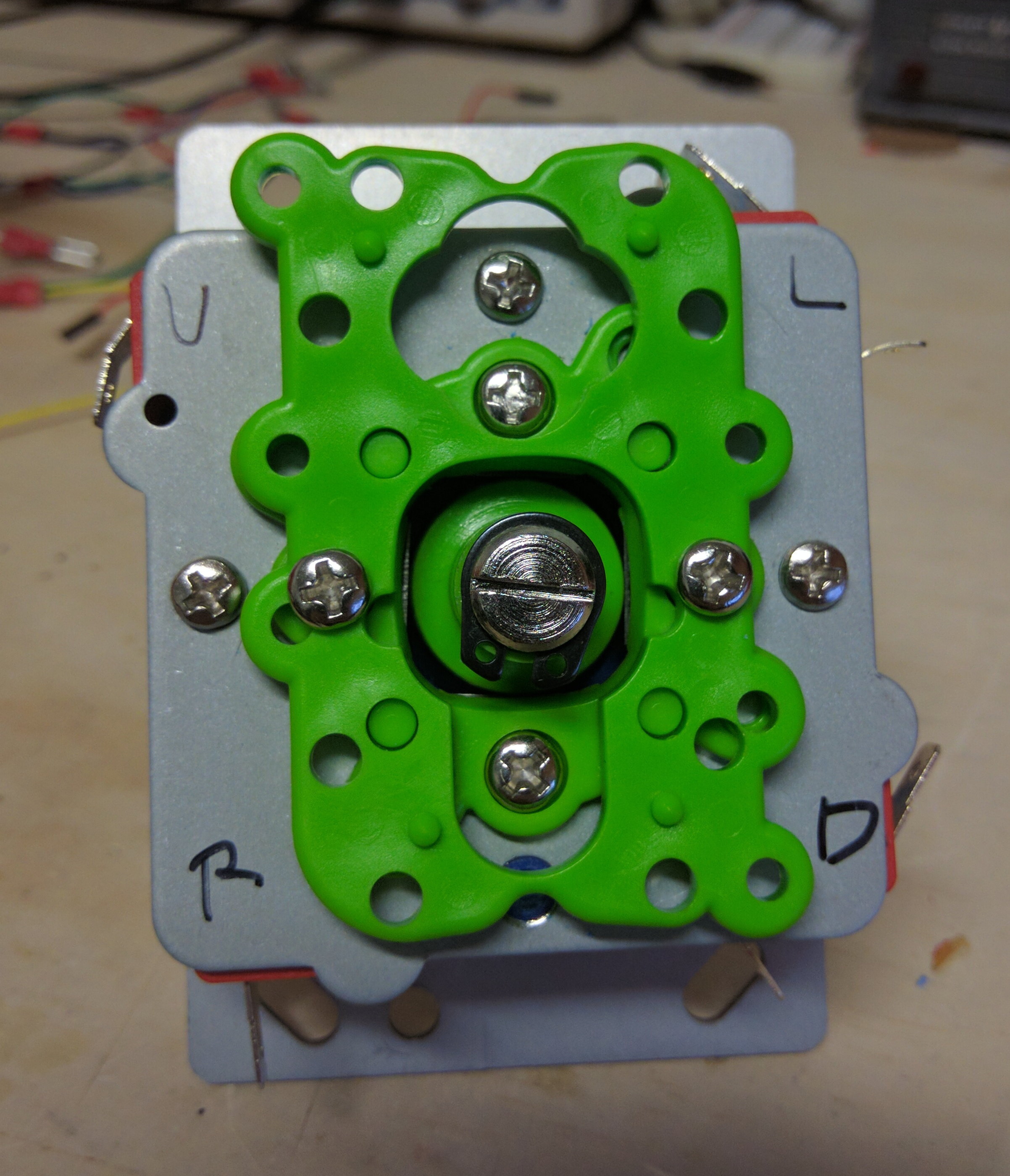
Once you have the orientation, unscrew the red ball from the top of the joystick handle, and remove the black washer as well. Unscrew the top metal plate, and feed the joystick from under the box lid. Secure the joystick by screwing the metal plate on top of the box. You'll want to mark where those holes are and pre-cut a hole for each screw as well. Replace the black washer, and replace the red ball.
Wiring
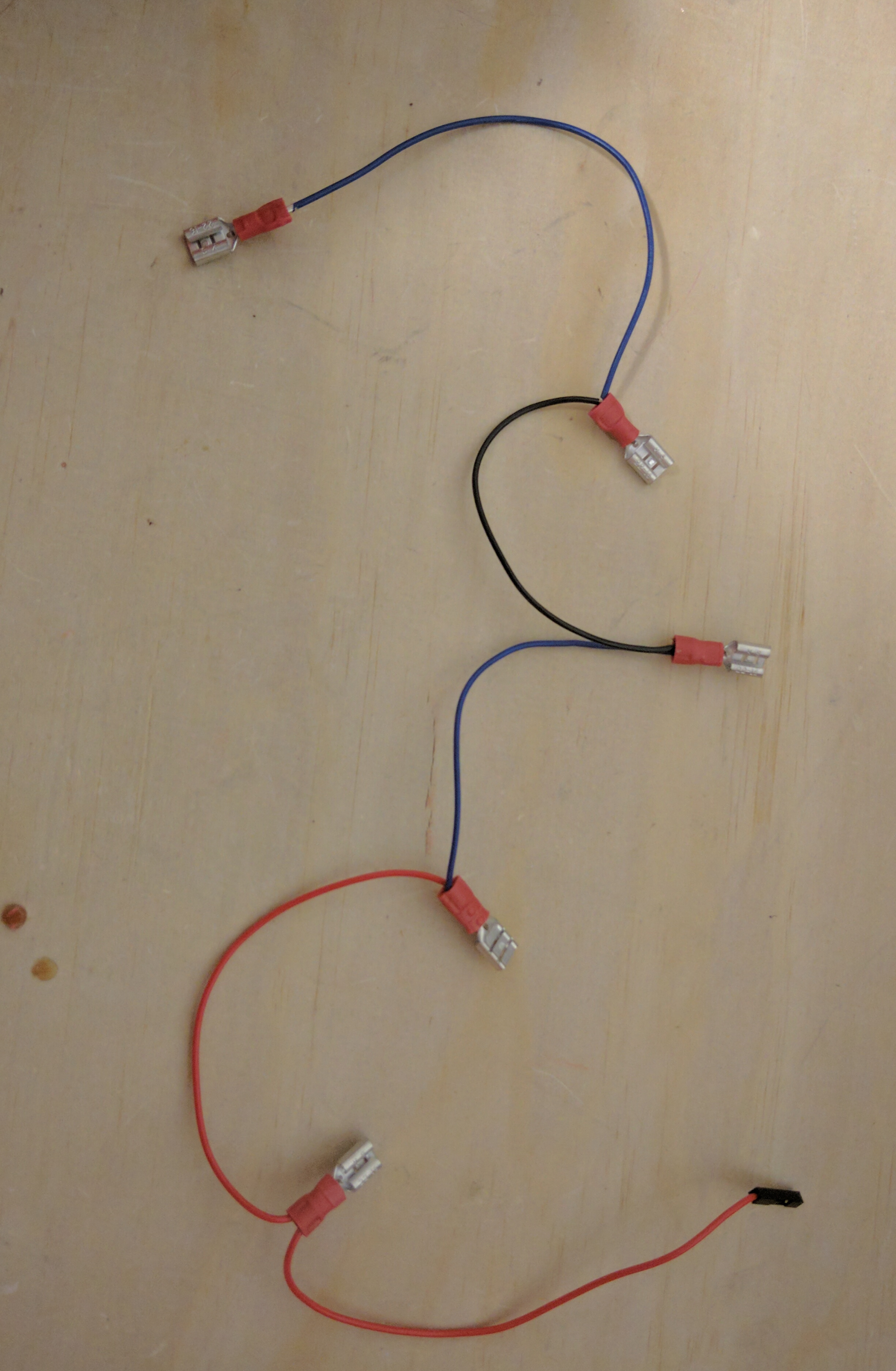
You may have noticed some 6" strands of wire and 20 female quick disconnects. You will need a pair of crimpers or there may be a crimp tool on your wire strippers already. You will build two wiring harnesses for ground. One wiring harness will have five quick disconnects daisy chained together for the buttons, and the other will have four quick disconnects daisy chained together for each ground pin in the joystick. Then nine individual wiring harness for each button and direction on the joystick. The ground on the button switches are the lone tabs on the long side of the switch. The same goes for the joystick.
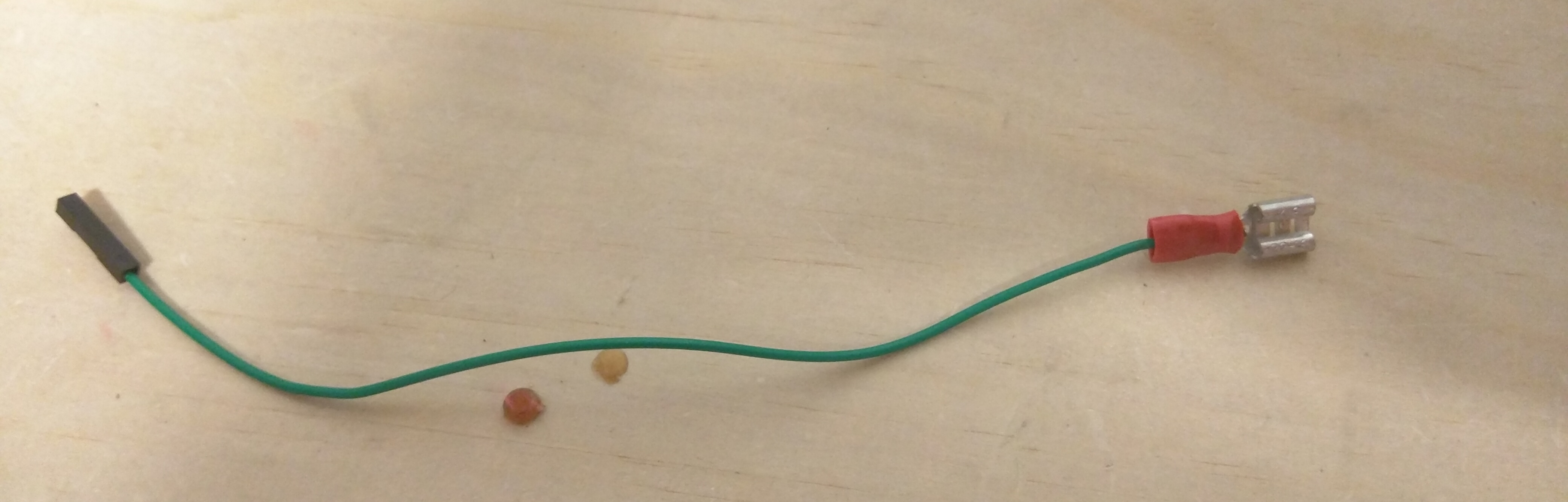
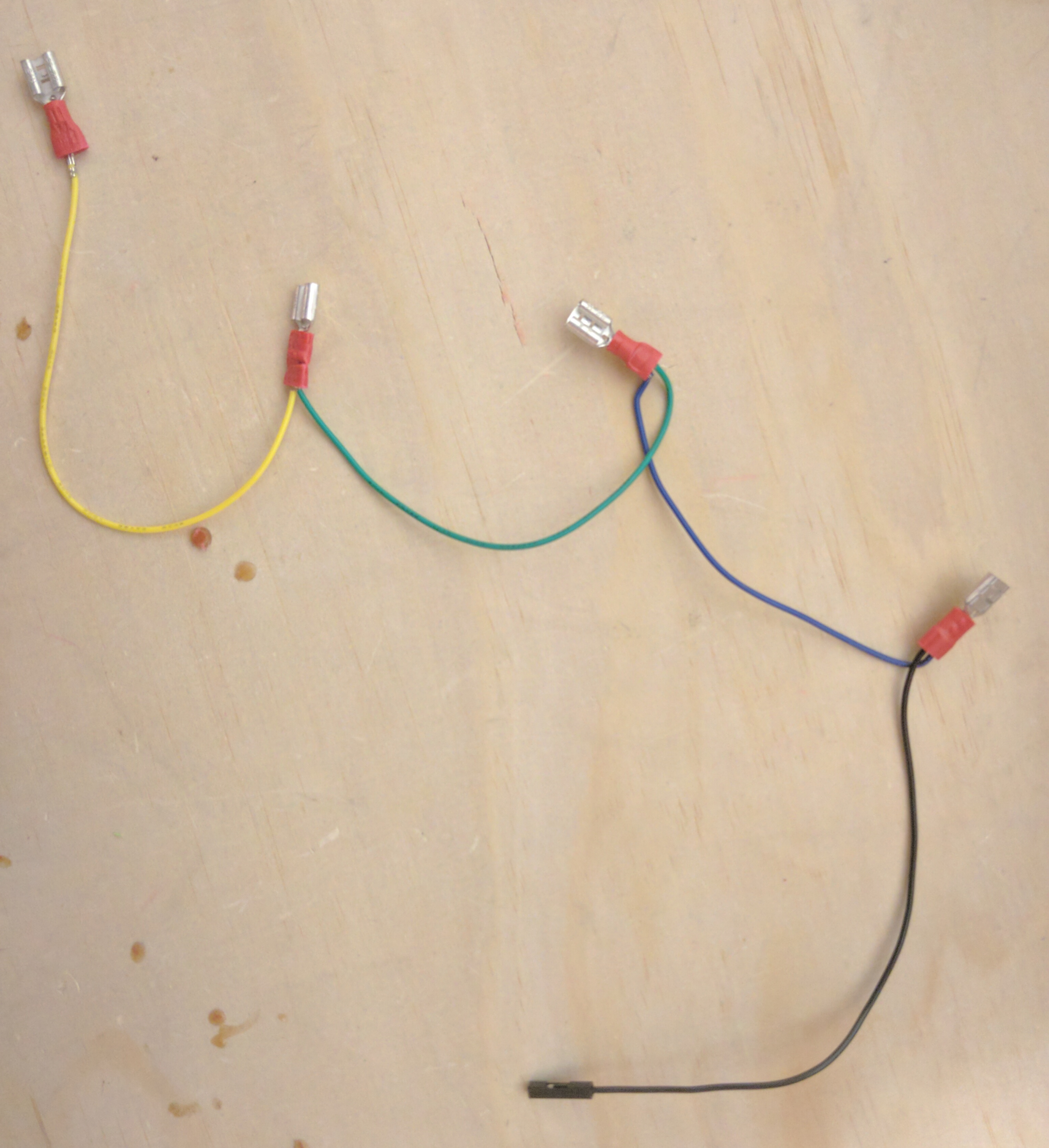
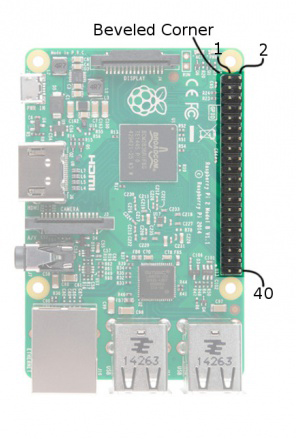
In the video, each button and direction was labeled along with its corresponding GPIO on the box with marker. Below is a picture of the mapping. The individual wiring harnesses are attached on the tab that is labeled "NO" (Normally Open). It is also labeled pin 3 on the switch. "Enter" is used as "start" and is mapped to Pin 21. "ESC" is used to back out of games and labeled "Select" (Trying to keep traditional controller vibes) on the box and it is mapped to pin 26.
See the image below for the correct orientation.
For the power, audio and monitor cables, cut three holes in the back of the box, and feed those cables through them. I'm using a set of powered speakers for audio. Close the box, and get ready to play.
