ProtoSnap LilyPad Development Simple Hookup Guide
 jimblom
The ProtoSnap Circuit
What's great about the ProtoSnap is all of the boards I mentioned above, sold separately, are mish-mashed and wired together. Before programming the Arduino board, it's important to know just how all of those boards are wired together.
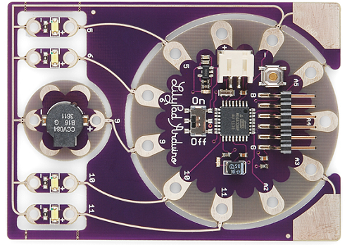
Each pin on the Arduino Simple Board is given a distinct number, which will be referenced in the Arduino code. Notice the white pin labels on the board - specifically those labeled 5, 6, 9, 10, 11, A2, A3, A4, and A5 - those are the pin numbers. They'll be used time and time again in your Arduino sketch.
On the ProtoSnap, these pins are wired up to LEDs or buzzers (or, in some cases nothing). If you want to control an LED, or activate the buzzer, it'll be important to know which pin they're connected to. There are a few ways to find this out: you can actually see and trace the wires -- the bronze-silver colored, squiggly lines running from one petal to the other -- or you can reference the pin number. Or, you can check back to this handy table:
| Arduino Pin Number | Component | Input or Output? |
| 5 | Left-most LED | OUTPUT |
| 6 | Middle-left LED | OUTPUT |
| 10 | Middle-right LED | OUTPUT |
| 11 | Right-most LED | OUTPUT |
| 9 | Buzzer | OUTPUT |
| A3 | Touch sensor | INPUT |
| 13 | On-board, green LED | OUTPUT |
To be clear, any of those pins could be configured as inputs or outputs. That input/output column is really only applicable when you're using this exact circuit.
The inputs with an "A" in their name are analog inputs. They're special. They can do everything a digital input can do, but they can also be used as an analog-to-digital converter. An ADC can read in a range of voltages, instead of just reading a high or a low. This makes them handy for sensing analog inputs (like the on-board touch sensor).