RedStick Hookup Guide
 MTaylor
Powering the RedStick
The RedStick was designed to allow two sources of power.
- Power directly from the USB port.
- Power with 2-6 volts on the battery terminals.
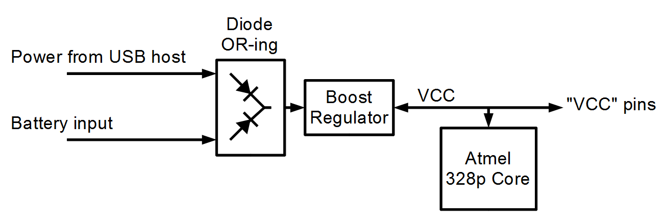
Functional Description
When power is applied to the USB port, it will not flow into the battery. Alternately, if the USB voltage is lower than the battery, power will not flow into the USB host.
To use AA cells, for example in a battery holder such as a 2xAA Holder with switch, solder the wires directly into the battery terminal holes, matching red to positive.
To use a rechargeable battery, such as a 1 Ah Lithium Ion battery, solder a JST connector into the smaller, 2mm spaced holes and attach the battery. Again match red with positive.
Notes on DC-DC converters
The RedStick uses a boost circuit to convert a low voltage ( > 2.0 volts DC ) to 5 volts DC. This DC-DC conversion is fairly common in today's world where a liner regulator is not efficient enough. This boost circuit measured around 83% efficient.
Here's a couple concepts to think about related to DC-DC converters
DC-DC converters and power
Ideally, DC-DC converters would be 100% efficient. In the math model, this means that power out = power in. So, if the converter is delivering 200mA at 5V, by the definition of electrical power, that's 1W (P = V * I). If we're consuming 1W from the output, we must be supplying 1W to the input. If the input is a battery at 3V, supplying 1W, it must be supplying 330mA. That's more than we're getting out!
As the input voltage to a DC-DC converter drops, the current consumption increases to maintain the output load.
This also applies to LED and CCFL bulbs that aren't dimmer compatible. As the dimmer decreases the voltage, the current increases and fries the dimmer circuit because it was designed for resistive loads (incandescents) that behave as Ohm's law indicates.
Drawbacks of DC-DC converters
The appeal of DC-DC converters is the low cost of the completed circuit. This is because inductors are used in place of transformers. The inductors operate at a high frequency so that the size can be made small, which makes them cheap. The control circuitry is a logic system that chooses when, and how fast, to operate the inductor in order to build up the necessary voltage on the output. This switching frequency can be seen as ripple on the output side of the DC-DC converter, depending on the loading of the circuit.
This DC-DC converter produces between 30 and 170 mV ripple in the 5kHz to 250kHz range, with optimal performance between 2.5-4.5 volts (typical battery voltages).