Servo Trigger Hookup Guide
 Byron J.
Expert Exercises
Customizing the Servo Trigger
The Servo Trigger was designed to make using servo motors easy, but it may not fit every application. You might need different timing, or different logic that interprets how the input is translated into the motor drive signal.
Since the heart of the Servo Trigger is a microcontroller, the firmware on that controller can be reprogrammed. And because the design is released as Open Source Hardware, the source code for the firmware is published in the device's GitHub Repository. You're welcome to download and modify it!
Toolchain
The Servo Trigger firmware was developed in Atmel Studio 6.2.1153, using a JTAGICE3 debugging module. The JTAGICE3 can configure and program the chip, and also offers a full-featured interactive debugger. You can pause execution and inspect the chip internals, which makes troubleshooting the application significantly simpler -- especially because the Tiny84 lacks a serial port that could print debugging information.
If you're using Atmel Studio, the /firmware/ directory in the repo contains the project and solution files.
While Atmel Studio makes a nice graphical front end and has a full-featured debugger, it is not required to recompile the firmware or reprogram the IC. You can use the command-line WinAVR tools, and program the board using an AVR-Dude compatible programmer, like our Tiny AVR Programmer. If you're going this route, Firmware\ServoTrigger\Debug contains the WinAVR compatible makefile.
Firmware Modifications
Timing
The range of transit times accessed by the T potentiometer is defined by a table of software values -- the table interprets pot position using an exponential curve, which allows for fine control of very short times on the low end, but still premits a useful longer range at the top. But perhaps these times don't fit your application especially well -- maybe you need extra resolution at the low end, or much longer times at the top end. You can change the timing table to do this.
The table is calculated using the "translation.ods" spreadsheet. Simply type the desired time in seconds into the green cells. The sheet recalculates the timing values, and updates the yellow cells. Cut and paste the yellow cells into the timelut array.
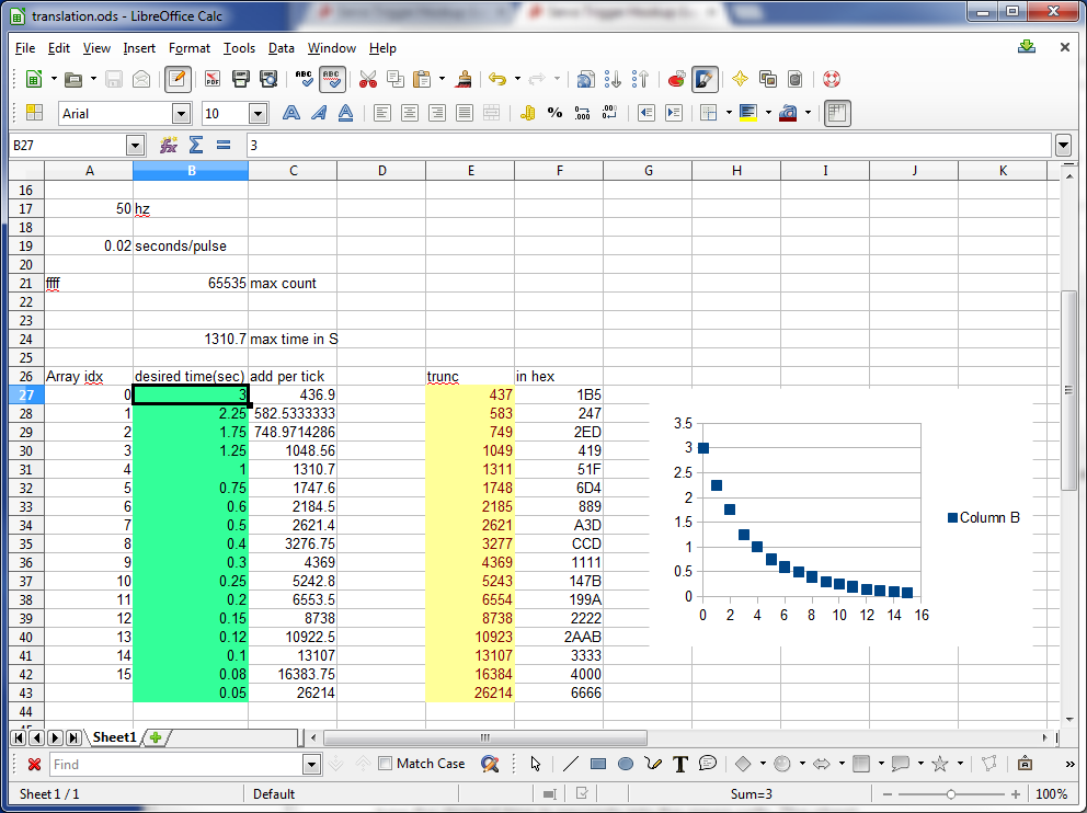
The table is only 17 entries long, which seems rather short -- but keep in mind we're using a microcontroller with only 8KB of flash memory and 512 Bytes of RAM -- we wouldn't want the timing table to fill the whole memory. To increase resolution between the table entries, the firmware performs linear interpolation to create more finely grained points in between.
Modes
The Servo Trigger comes with a couple of response modes that should be useful for most servo control needs, but in the case they're not a good fit, they can be modified.
There are several other modes hidden in the source file. In addition to the two default modes, there are three other modes. You can select among these by changing the compile-time symbols in the project. In Atmel Studio, select the "Servo Trigger" tab, then navigate to "Toolchain-> AVR/GNU C Compiler->Symbols" item.
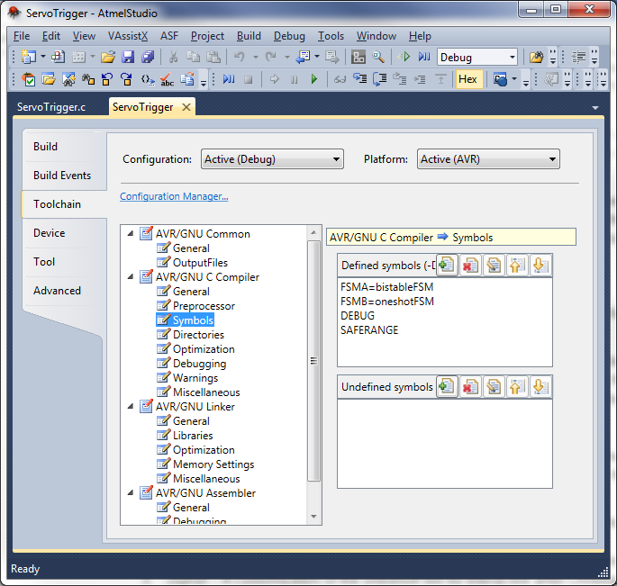
If you're using the command-line tools, the symbol definitions are found in the compiler invocation in the Makefile.
The FSMA and FSMB symbols determine which modes are programmed on the Servo Trigger. FSMA defines the unjumpered (default) mode, and FSMB defines the jumpered mode. There are five modes currently defined in the source file.
bistableFSM- The default mode - when the input is asserted, it moves from position A to B. While input is held, it will stay at B. When released, it moves back to A.oneshotFSM- Does a complete cycle every time the input is asserted - from A to B, then back to A.ctpFSM- A customization of the oneshotFSM for interactive artist Christopher T Palmer, which allows the B-to-A return cycle to be interrupted by a fresh input actuation.togglingFSM- Each time the input is asserted, it changes from A to B, or B to A. This mode is especially useful for driving continous rotation servos.astableFSM- When the input is asserted, it cycles back and forth between A and B. When the input is inactive, it sits where it was.
You can put any mode in either slot, or even put the same mode in both.
Implementation Details
As you may have guessed from the names, the modes are implemented using Finite State Machines. Finite state machines are a design concept the defines a set of states, and a corresponding set of rules that determine how to transition between the states.
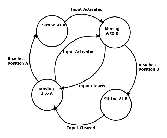
Within the Servo Trigger, each mode uses the same basic set of states, which in turn describe how it drives the servo. The states are:
- Sitting at position A.
- Moving from A to B.
- Sitting in position B.
- Moving from B to A.
The rules that define when the states can change can alter the behavior in significant ways. The different modes of the Servo Trigger are all implemented using the same states, but with different transition rules.
FSMs are commonly illustrated using "bubble diagrams," which draw the states as circles, and the rules as arrows between the circles. Here's the bubble diagram for the bistable FSM.
Building New State Machines
In the Servo Trigger, a state machine is implemented as a single function, which contains a switch statement wherein each state is a case. At the start of every PWM cycle, the state machine function is called to determine the pulse width, and possibly move to new states.
If you want to implement a new state machine, it can be useful to start by drawing the bubble diagram.
If your new FSM is a slight alteration to an existing one, the next best place to look at the existing FSMs -- it might be as simple as transplanting a state transition rule from one function to another. If your FSM is more ambitious, it's still useful to read and understand how the FSM interacts with the rest of the firmware.
Your application may need a subtle variation of an existing FSM, or a complete re-formulation. Since the source code is available, you're welcome to modify it to suit your needs!