SparkFun BME280 Breakout Hookup Guide
 MTaylor
Assembly
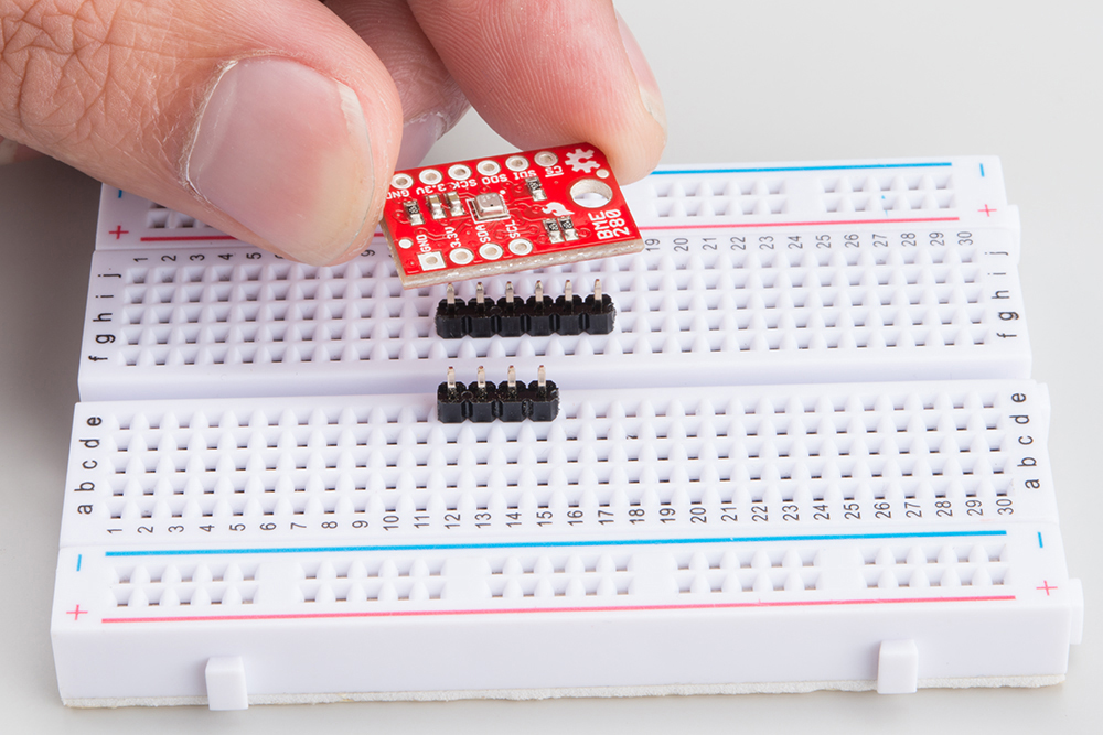
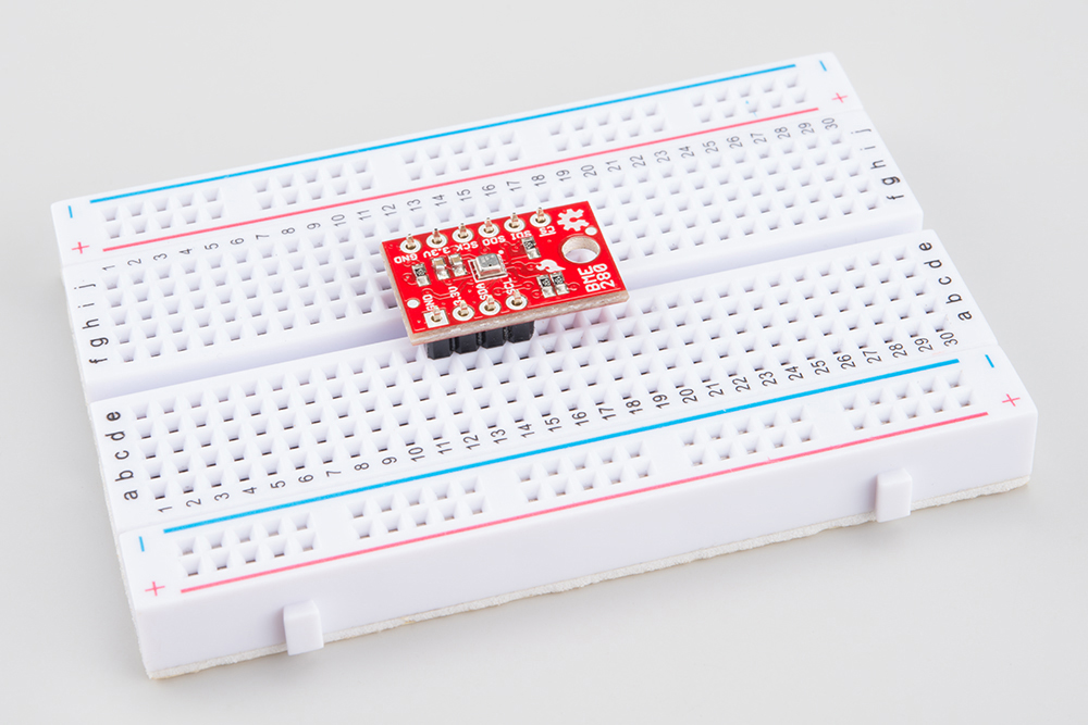
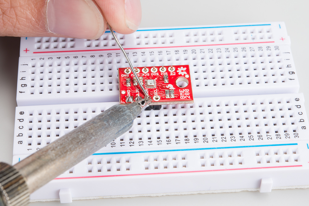
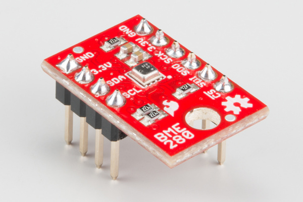
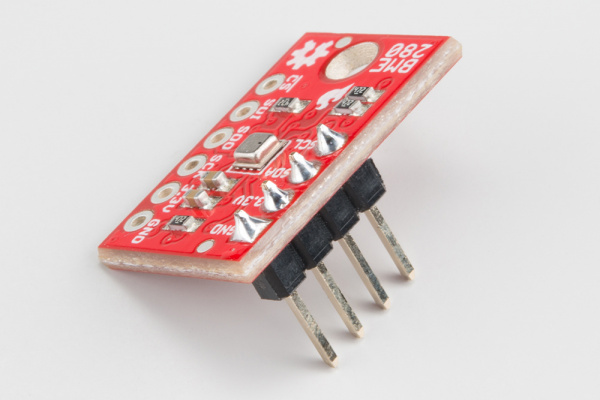
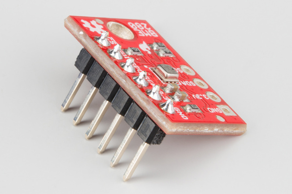
Attaching the headers
If you got a board without headers, you will need to solder to the PTH pads. Regular wires can be soldered in, but for a more configurable breadboard experience you may want to attach headers.
 |
 |
 |
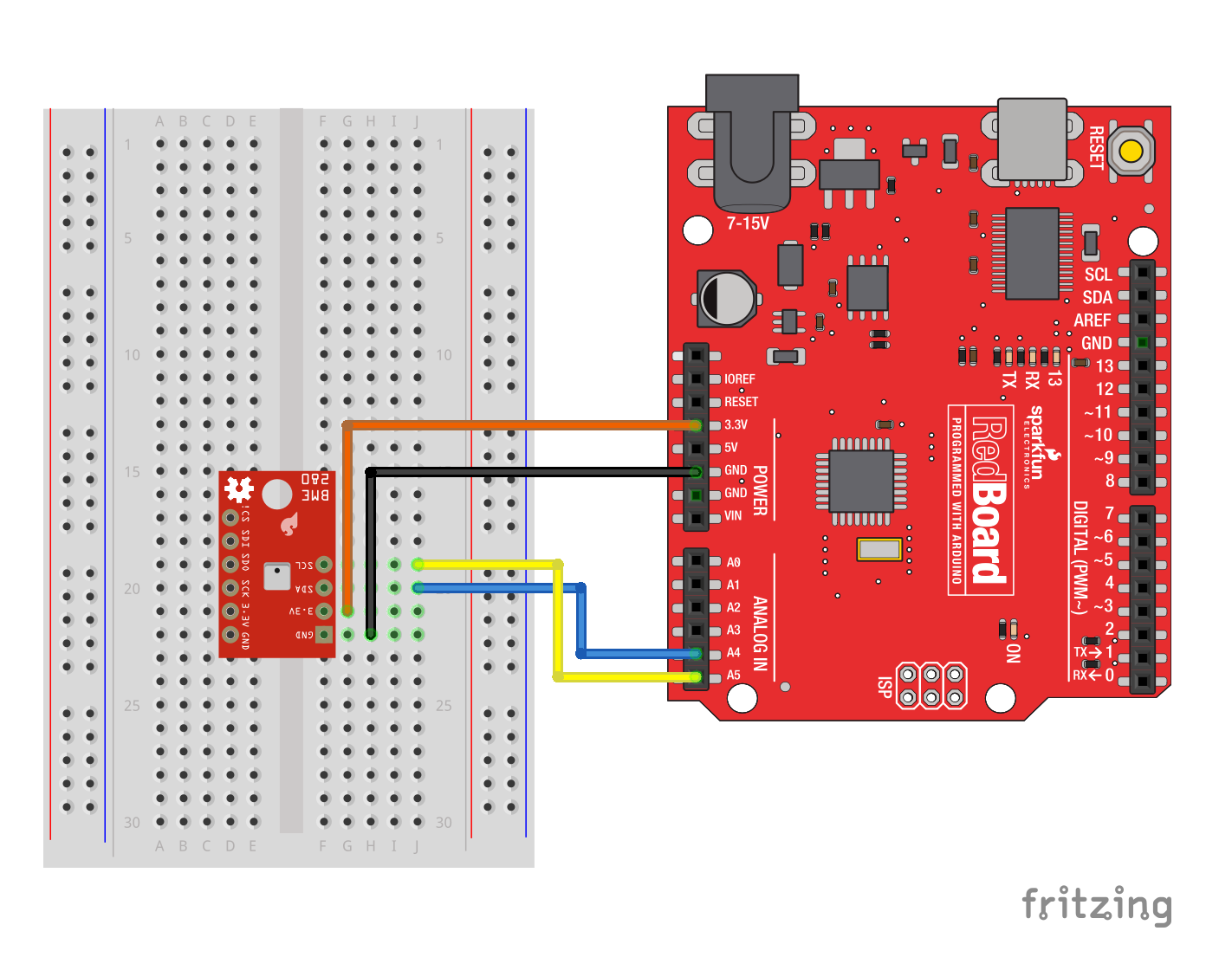
I2C Connection
The sensor pulls the I2C lines to 3.3V, so they can be directly connect to the redboard's A4/A5 pins, or the SDA/SCL pins (as long as they're configured by Wire). Make sure to power the sensor from 3.3v! The power and ground pins are connected, so you only need to connect to one side.
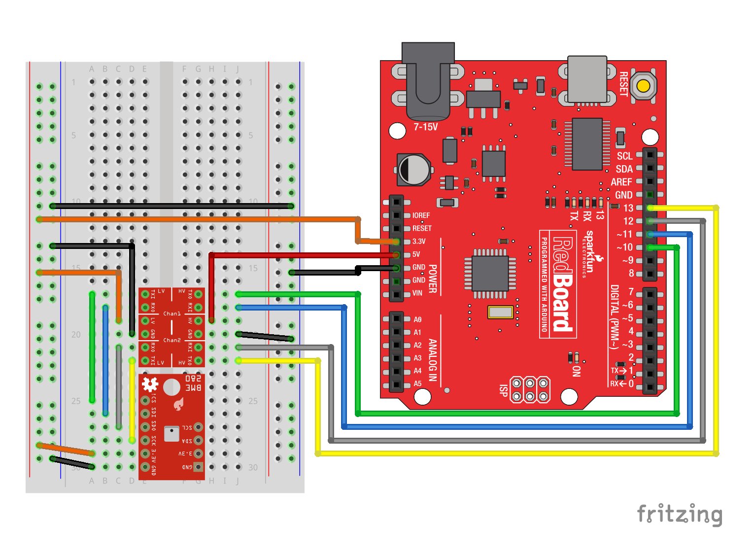
SPI Connection
The SPI connection isn't quite straightforward when connected to a RedBoard. The Logic Level Converter is required to bridge between the 3.3v requirement of the BME280 and the 5v IO of the RedBoard. 3.3v microcontrollers such as the fabulous Teensy 3.2 can be directly connected.