SparkFun gator:soil Hookup Guide
 Englandsaurus
MakeCode Example
Now that you have added the gator:soil extension to the Editor, lets start with some example code. Plug the micro:bit into your computer using an USB micro-B cable after you have assembled your hardware with the instructions from the previous section. The micro:bit should appear on your computer as a removable storage device.

To upload new code, this is where you will be copying the downloaded .hex file to later.
Block Function
Get moisture on pin _____ in _____ using power pin _____
This is a value block as indicated by the block's shape. There are three drop down menus with selectable options for how the sensor is wired and the output value of the block. Below is a description of the available menu options (from left to right):
- ADC or SIG Read Pin- This pin is used to read the
SIGoutput of the sensor. The pin options are as follows:P0toP20P5toP9&P11toP20: Digital pins that can't be used as indicated with(write only).- Pins
P0toP4andP10: Analog pins that can be used, but the only pins that are available on the gator:bit (v2) areP0,P1, andP2.
- Measurement Value
This designates the output value that is read. There are two options:moisture- A value ranging between 0 and 1.adcvalue- A 10-bit integer value from micro:bit ADC ranging between 0 and 1023.
- Power Control Pin
This pin is used to control when the sensor input power (PWR). The pin options are as follows:P0toP20- Only pins
P0-P2,P5,P8,P11,P13-P16, andP19-P20are available on the gator:bit (v2).
- Only pins
forever loop, reducing the life span of the probes.System Calibration
To get any sort of useful data out of your Soil Moisture Sensor, it is advised that you calibrate it to whatever soil you plan to monitor. Different types of soil can affect the sensor, and you may get different readings from one composition to the next. Before you start storing moisture data or triggering events based on that value, you should see what values you are actually getting from your sensor.
Once you have an idea what values your sensor is outputting in completely dry and completely wet situations, it's time to calibrate your sensor for the specific soil you want to monitor. Test your soil when it is as dry as possible, then measure it when the soil is completely saturated with moisture. Getting these values and comparing them to the ones from the previous calibration will give you the best insight into what values mean for your specific plant and soil. This test may take some trial and error and patience. Be careful not to splash water onto the sensor or over-water/under-water your plants during these tests.
Once you have a good handle on the values you can expect, you can map function under the Pins library block to adjust your results.
Basic Read
Below, is a simple example of how to take simple measurements from the sensor. The example uses a extremely short 10 second delay between measurements, primarily for demonstration purposes. To use this example, there are multiple options for accessing the .hex file:
- Replicate the block functions from the display below to copy the example project. Then download the
.hexfile. - Expand the display widow to pull up the example project. Then download the
.hexfile. - Use this link to pull up the example project. Then download the
.hexfile. Download the
.hexfile from the button below or the link on the bottom of the display.
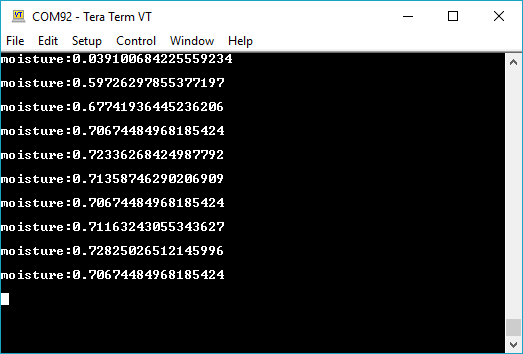
The output is redirected over the serial port to avoid conflicts on pins P0 and P1, which are also used for serial communication. To read the sensor values, pull up your favorite serial terminal emulator. Then, connect to the serial port that the micro:bit is on; the default baud rate is 115200 bps. Below, is an example of the sensor output for the example code.