SparkFun Qwiic RFID-IDXXLA Hookup Guide
 Elias The Sparkiest
Hardware Overview
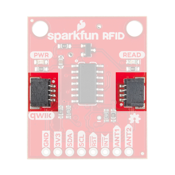
Qwiic Connectors
This is a Qwiic product but not a "pure" Qwiic product. You'll still need to solder or connect the interrupt pin if you decide to use that to indicate when an RFID card has been read (more on that later). Outside of that, Qwiic is an eco-system designed for I2C devices that allows you to prototype quickly without needing to solder anything. Just plug your Qwiic product into a Qwiic capable microcontroller and you're good to go! There are two on this product which means you can daisy chain the product with other I2C devices, like a Qwiic Keypad for example.
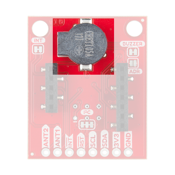
Power
The SparkFun Qwiic RFID ID-xxLA is a 3.3V system. You can power the product with a Qwiic cable plugged into a capable microcontroller. You can also provide power through the 3V3 pin on the header.
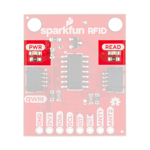
LEDs and Buzzer
When you provide power to the board you will see the onboard red power LED light up. There's another LED opposite the power LED labeled READ. This blue stat LED and the onboard buzzer will light or beep respectively when an RFID tag is brought into range.
 |
 |
RFID Modules
There are three ID-xxLA options in our catalog that are listed above in the Introduction: the ID-3LA, the ID-12LA, and ID-20LA. If you purchased the SparkFun RFID kit then it includes the ID-12LA and RFID cards that you need. Pictured below is the ID-12LA plugged into the Qwiic RFID.
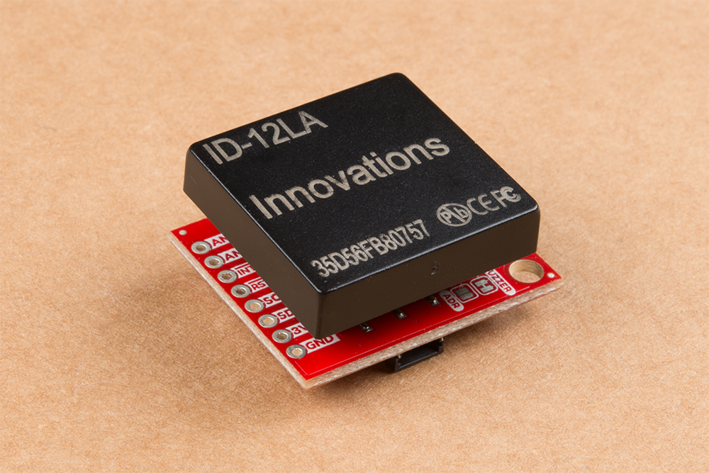
Each option is similar but there is a small variance in power consumption which translates into different read range capabilities. The ID-3LA is designed to be used with an external antenna which will get you 30cm of range. The ID-12LA and ID-20LA have a range of 12cm and 18cm respectively.
When plugging in your module, just take care that the side with less pins goes into the header with less pins.
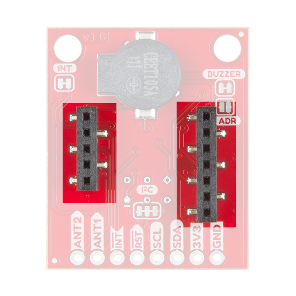
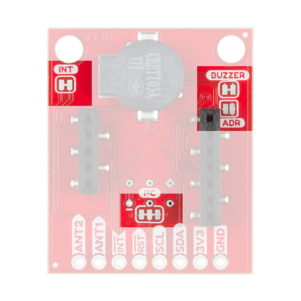
Jumpers
There are four jumpers on the header side of the product. Facing the product with the buzzer at the top, you'll see a jumper on the left side labeled INT. The interrupt pin can be disconnected here by cutting the trace. Now moving to the bottom near the header is a jumper labeled I2C that connects the I2C pull-up resistors to the I2C data lines. On the right side is a jumper labeled Buzzer that disconnects the buzzer when cut. This will disable the beeping sound when a RFID card is in range. Finally, the ADDR jumper allows you to change the default I2C jumper from 0x7D to 0x7C.