Stepoko: Powered by grbl Hookup Guide
 MTaylor
Hardware: The System and Power Supply
Powering the Stepoko
Stepper motors take a lot more current than most hobby circuits. The Stepoko can supply up to 2.0A each per coil! To get that kind of power, an ordinary wall adapter won't suffice. Apply 12-30 VDC to either the barrel jack or screw terminals, but not both. Use either a power brick or a Benchtop Supply of some kind. Make sure the supply can generate about 3 times the single-coil current for a 3-axis setup. Because of the switching nature of the stepper motors, the maximum current for a single winding is greater than the total current required to run that motor.
Use the following formula:
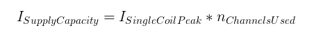
For instance, if two channels are used and set to 1A each, a 2A supply is required.
After power is attached, the blue power LED should light illuminate. If it doesn't, or if the reverse protection LED lights up, remove power and check voltage/polarity of the supply.
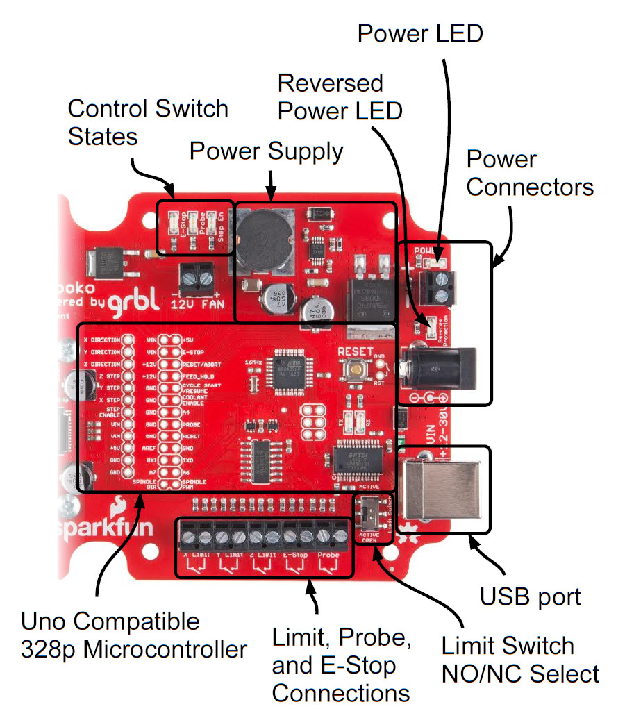
The Embedded ATmega328p Microcontroller
The Stepoko is actually an Uno compatible ATmega328p! It's just an Arduino with a grbl shield attached. This is evident by looking near the USB port where the familiar FTDI, Atmel IC, reset button, and even the SPI 2x3 header can be found. In this area, we've even broken out all of the pins that are associated with the microcontroller and power supplies. If you peek at the back of the board, there's a chart in silkscreen that matches the grbl pin functions to the Arduino pin naming convention. It's open source! You can do what you want to it.
To use the microcontroller, attach a USB cable and let your computer enumerate the device as it would with an Arduino. After that, you could program it with the Arduino IDE. It comes with grbl 0.9 though, so don't program it unless you absolutely have to. Even if you revert back to grbl, the grbl settings will be lost and you'll have to program them all in again.
Connecting the control switches
The Stepoko supports
| Pin Name |
Function |
Location | Wiring |
|---|---|---|---|
| E-Stop |
Disengages the motor drivers |
Breakout pins Screw terminals |
Closed on 'Run' while connected to terminals. Drive high for 'Stop' on pin headers - remove U6 for use |
| Reset/Abort | Breakout pins |
Internally pulled high. Close to ground for function. |
|
| Feed Hold |
Pauses the current job |
Breakout pins |
Internally pulled high. Close to ground for function. |
| Cycle Start /Resume |
Restarts the paused job |
Breakout pins |
Internally pulled high. Close to ground for function. |
| Probe | Detect material |
Breakout pins Screw terminals |
Normally open, connected to terminals. Drive high for active on pin headers - remove U6 for use |
| Reset | Resets the microcontroller |
Breakout pins and 1x2 header by reset switch | Pulled up by design. Close to ground to reset microcontroller. |
| X,Y, and Z Limit |
Stops all motion |
Screw terminals |
Normally open or closed set by switch and wired across terminal pair. |
 |
 |