Teensy XBee Adapter Hookup Guide
 MTaylor
Hardware Assembly
There are a few theoretical steps to get a project working with the Teensy and XBee that will be discussed.
Here are the basic steps:
- Determine how to power the system
- Connect the hardware
- Configure the XBees
- Establish serial over XBee (this tests all systems - highly recommended)
- Build and test the actual project
Determine How the System is Going to be Powered
Powering Low Power XBees Default Solder Jumper
The XBee requires around 3.3V to operate, depending on the model. The Teensy 3.1 and 3.0 have an on-board regulator that outputs 3.3V, which is perfect, but only for lower power radios that consume less than 100mA.
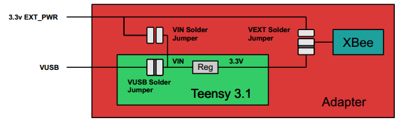
This is the default configuration. The internal regulator can supply about 100mA of current for 3.3V use, including what is consumed by the Teensy and things on the 3.3V rail. XBees up to 2mW (non-"pro" models) consume up to 40mA, so, if you have a basic XBee, this is probably the route for you. Supply 3.7V to 5.5V (or USB power).

Powering High Power XBees EXT Solder Jumper
If you have a higher powered XBee, or more than 100mA of load on your 3.3V rail, you'll need to disconnect the XBee from the Teensy 3.1 and 3.0's internal regulator and supply 3.3v from somewhere else. A Breadboard Power Supply Stick is a possible power source for this application.
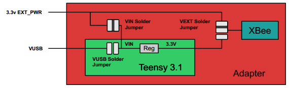
In this case,
- switch the PWR's solder jumper from the TNSY side to the EXT side
- short the jumper pad between VIN and EXT_PWR
- cut the trace between the Teensy's USB PWR jumper
| Example | Notes |
|---|---|
 |
switch the PWR's solder jumper from the TNSY side to the EXT side |
 |
short the jumper pad between VIN and EXT_PWR |
 |
cut the trace between the Teensy's USB PWR jumper indicated by the red line in the image |
Now both the Teensy and XBee are powered from the ext power pins, so you'll need to provide power and plug in the USB if you want to reprogramming the device.
Connect the Teensy to the XBee.
The XBee fits straight into the adapter. Make sure the XBee outline matches the silkscreen on the adapter.
The Teensy and adapter come as PCB without headers. Check out the Sparkfun Getting Started with the Teensy for example of how pins and sockets can be attached.
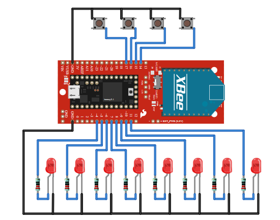
Connect Periphery Equipment
Use the outer holes to connect all manor of switches and sensors that you wish to read from the Teensy. This tutorial makes a controller, so buttons and LEDs are connected as shown in this diagram.
Configure the XBees
The XBees are shipped with a default configuration (see XBee documentation). Even if they work out of the box, you'll be using the default IDs and will be suseptable to unseen XBees interfering with your system (because some other designer had the similar thought, "I'm the only one here, why not use the default IDs.") Also, you can change other more advanced features once you're familiar with the concepts.
The parameters used for these demos
- ID/PAN ID = A5F1 - This can be any 16 bit hex value used to identify your network. Make sure it is the same for both radios and unique in your area. A5F1 was randomly chosen for this guide. You can choose any ID for your network.
- Data rate = 9600
- Parity = N
- All others at factory default
Configuring XBees with USB based explorers
- Socket an XBee into the explorer matching the silkscreen orientation
- Plug the explorer into the USB port
- Open X-CTU
- Select your explorer's serial port
- Querry the XBee to make sure the drivers are working
- Read the configuration from the XBee
- Modify the parameters
- Write the new configuration to the XBee
Repeat this process so that both XBees have the new configuration.
Power the System!
Apply to the system. Powering through the Teensy, use 3.7 to 5.5v. Alternately, supply regulated 3.3v to the EXT_PWER pins. Does the power LED on the adapter illumniated? It shows if power is getting to the XBee. Try running the blink sketch to determine if the Teensy is really powered and ready to recieve firmware.