- Home
- Product Categories
- Power Accessories
- SparkFun MOSFET Power Switch and Buck Regulator (Low-Side)


SparkFun MOSFET Power Switch and Buck Regulator (Low-Side)
Does your microcontroller need to control a high-voltage item, like a 12V LED strip, while also needing to be powered? Do you want to avoid having multiple power adapters and microcontrollers for your project? The MOSFET Power Switch and Buck Regulator (Low-Side) is one product we needed at SparkFun, so we figured other folks might have the same problem. Power the board with up to 12V and control up to 10A, all while providing a sweet 3.3V to your control board.
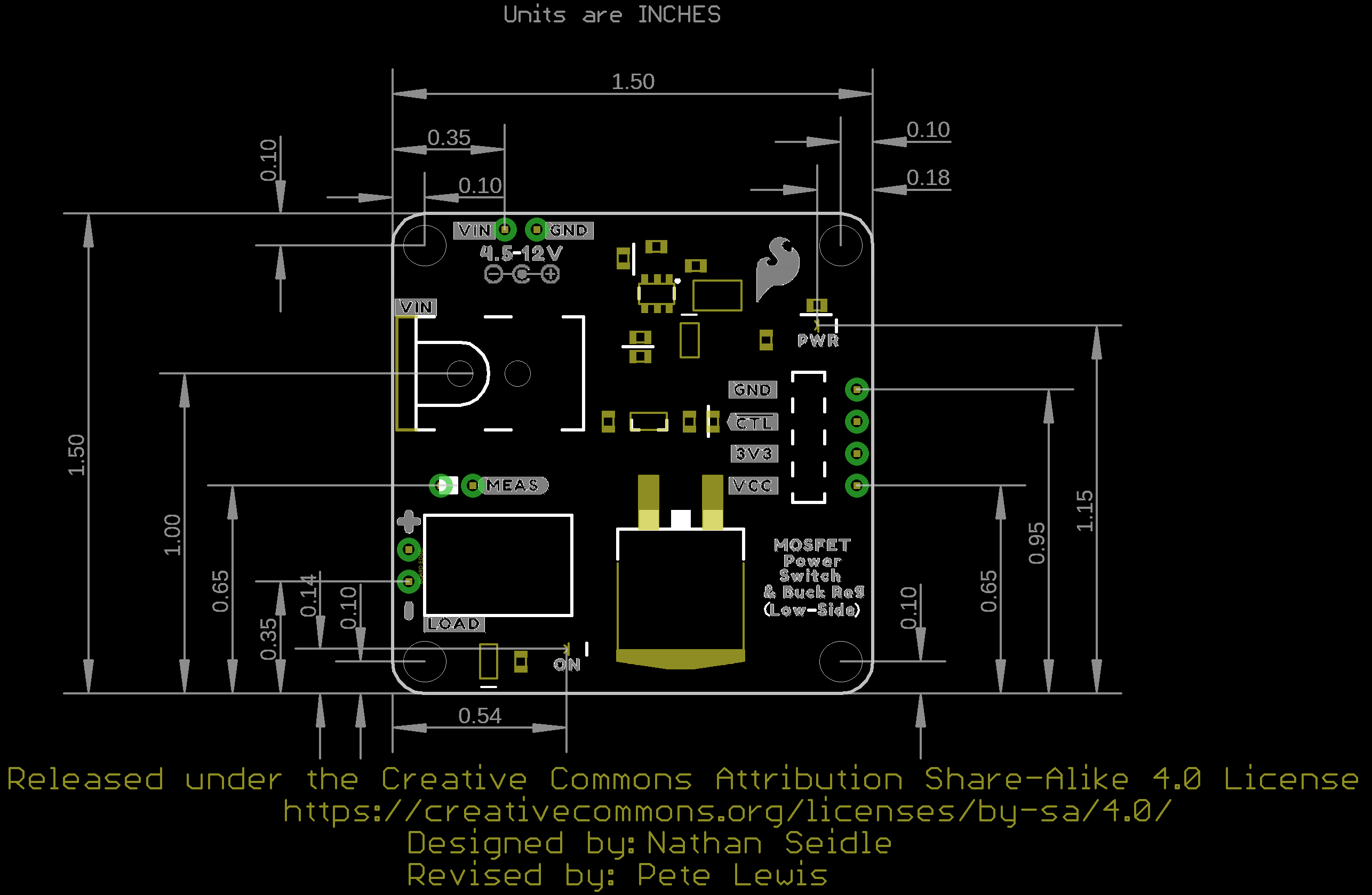
The SparkFun MOSFET Power Switch and Buck Regulator (Low-Side) combines two circuits into one board: an LMR14203 buck regulator configured to output 3.3V and an N-channel MOSFET (PSMN7R0-100BS) configured as a low-side switch. A flyback diode is also on the load side for devices with back EMF! Simply pull the CTL pin low to activate the load.
Various connectors (barrel jack, female header, and poke-home) are provided to connect a power supply to a microcontroller of your choice (Arduino, micro-bit, Raspberry Pi’s microcontroller) and load them together. VCC, 3.3V, CTL, and GND are also broken out through 0.1" spaced PTHs for those who prefer to solder. Two LEDs (PWR_LED and ON_LED) indicate when there is 3.3V and whenever power is applied to the load. Jumpers are included on the back to disable the LEDs. A MEAS PTH jumper is also included for those interested in precisely measuring the current consumption of the system.
Note: While the MOSFET is rated to 100A/100V, we don't recommend you go much above 10A as the PCB polygon pours and traces become the limiter.
- Input Voltage Range: 4.5V to 12V
- LMR14203 Step Down Voltage Regulator
- Configured to Output 3.3V/300mA
- PSMN7R0-1000BS N-Channel MOSFET
- Configured as a Low-Side Switch
- Connectors
- Input: 5.5mm x 2.1mm Barrel Jack (Center-Positive)
- Output: Poke-Home Connectors
- Control: 1x4 Female Headers
- 0.1"-spaced PTHs
- Built-in Flyback Diode on Load
- LEDs
- PWR
- ON
- Jumpers
- PWR_LED
- MEAS
- ON_LED
- Dimensions: 1.50" x 1.50" (38.1mm x 38.1mm)
- Weight: 9.9g
SparkFun MOSFET Power Switch and Buck Regulator (Low-Side) Product Help and Resources
Understanding Thermal Resistance
May 14, 2020
Discussing what thermal resistance is, how it’s used for thermal management, and how to maximize the life of your project.
Comments
Looking for answers to technical questions?
We welcome your comments and suggestions below. However, if you are looking for solutions to technical questions please see our Technical Assistance page.
Customer Reviews
4 out of 5
Based on 2 ratings:
Worked great, got me out of a pinch
For three years my arduino chicken coop door kept the girls safe but the major design flaw (me not being a power engineer) was that the CPU and the relay coils had to be powered by batteries. If they ran low, the birds would have to be let out manually. The thing broke down finally just before I had to travel.
This little breakout board made it possible for me to whip up a new version that would never run out of juice. The only problem I had with it is that I had to get 12V relays and be very careful to isolate the relay coils with a transistor switch so the load of the actuator switching didn’t jolt the CPU. I found that I could activate the relay and then switch the load with this board, and the power seemed to flow pretty smoothly. Maybe I could ramp up the actuator with PWM on the switch to further improve it? Anyway thing’s working great. Money well spent.
Pretty good... but
So I had a use for this part and I tried it out straightaway. It works as advertised and does a good job, but I wish: 1. That the load connects were screw terminals. The plastic on my terminals shattered on the first use. 2. My Arduino needed 5V not 3.3V so I had to change resistors to get the voltage I needed, although Sparkfun did provide good documentation for me to make that change. Still, I would have liked a simpler way, like a solder pad cut/jumper. 3. Finally I wish that the input and output load solder pads were a little larger. I had molded barrel jack connectors with cables that were slightly too large for the provided pads. I suspect many people will have the same issue.
So good part. Does what it says. Please consider my comments if you make a revision.
Curious why the MOSFET is on by default by the gate being pulled up rather than being pulled down?