
Pulse a LED
Anyone can blink a LED,
but you'll really impress your friends* if you can pulse a LED!
There are numerous ways you could go about this: use separate "for" loops to ramp the brightness up and down, retrieve values from a look-up table, etc. It turns out there's an easy and effective way to do this using trigonometry. If you don't know what that means, or DO know and are scared, don't worry - it's very simple. I used this technique on the Elevator TARDIS to generate the pulsing blue light on top of Doctor Who's time machine, but it's also great for warning lights, art projects, and just plain looking cool.
Instead of boring you with theory, let's jump right in with an example. Copy and paste this into the Arduino of your choice, and hook up a LED and resistor to pin 11: (This example requires a pin capable of PWM, hence pin 11)
const int LED = 11;

void setup()
{
}

void loop()
{
  float in, out;

  for (in = 0; in < 6.283; in = in + 0.001)
  {
    out = sin(in) * 127.5 + 127.5;
    analogWrite(LED,out);
  }
}
That's pretty neat! But that code's pretty weird... what's going on here?
Waves 101
If you ever had a trigonometry class, you probably learned (and may have forgotten) about the sine function. (If you haven't taken trigonometry yet, you'll be able to impress your teacher with this information).
Sine is a function (you put a number in, you get a number out) that generates sine waves. Sine waves appear in nature all the time (ocean waves, audio waves, radio waves, pendulum motion), and because they vary smoothly over time (and are easy to make, as we'll see below), we'll borrow them to make our LED vary smoothly between on and off.
In the Arduino, the sine function is named sin(). It takes a floating-point value (known as a "float") as an input and returns a float as an output. Unlike integers (whole numbers), which you use for most things, floating-point values give you the ability to use decimal points (such as 3.14159). The most basic equation for sin() is:
out = sin(in)
For reasons that we'll gloss over for the moment (see Wikipedia if you're curious), the input number is actually an angle. When you vary this angle from 0 to 360 degrees (all the way around a circle), the wave will complete one full circuit. If you step through a bunch of angles and graph the output of sin(), you'll get a sine wave:
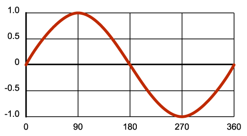
In this graph, the numbers you put into the function are along the bottom, and the number the function returns are on the left. For example, if you put in 90 degrees, you'll get back 1.0. By stepping through the intermediate values between 0 and 360, you can generate a nice smooth wave.
Rule #1
Now's a good time to learn rule #1: sin() doesn't want the angle in degrees, it wants it in radians. Radians are angles based on pi. When you start from an angle of 0, halfway around a circle (180 degrees) is pi radians (3.141), and all the way around a circle (360 degrees) is 2 * pi radians (6.283). (If this sounds familiar, it is related to the circumference of a circle being 2 * pi * the radius. More at Wikipedia). So, to put angles into sin(), use numbers between 0 and 2 * pi like this:
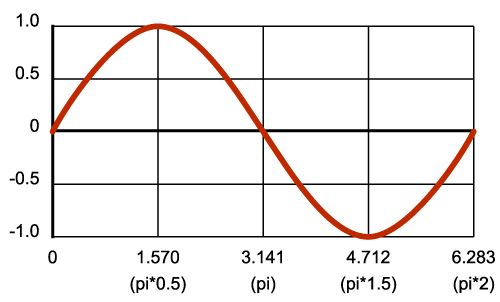
This explains the weird numbers in the "for" loop in the above code:
for (in = 0; in < 6.283; in = in + 0.001)
What we're doing is stepping along the wave, with input values from 0 to 6.283 (2 * pi). We're stepping by 0.001 so we get a lot of intermediate points which makes a very smooth curve, and incidentally slowing the computer down so the pulse isn't too fast. (More on modifying the speed in "Tips" below).
Home on the range
Next let's look at the output. The sine function will always return a floating-point number that ranges from -1 to +1. You can see this in the above graphs (look at the output numbers on the left side). This is a slight problem for us, since we want to use the analogWrite() function to drive the LED at various brightnesses; analogWrite() takes a value from 0 to 255, not -1 to +1.
To solve this problem, we'll add a bit more math to our equation:
out = sin(in) * range + offset
This will multiply and shift the -1 to +1 output to anything we want!
Here's a shortcut when picking range and offset: if you're trying to get to a number that ranges from 0 to n, use 1/2 n for both the range and offset. For example, we want our wave to range from 0 to 255 for analogWrite(), so we'll use 127.5 for both our range and offset (127.5 = 255 / 2). Multiplying -1 to +1 by 127.5 gives us a range from -127.5 to +127.5. (Multiplication always happens before addition when the computer is processing an equation.) Then when we add in the offset of 127.5, we get a range from 0 to 255! This explains the other line of code:
out = sin(in) * 127.5 + 127.5;
Which gives us our final input-to-output graph:
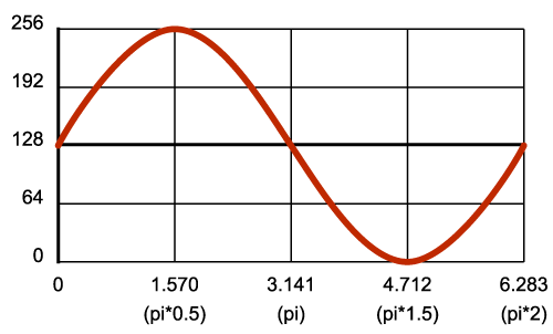
Now when you step the input from 0 to 6.283, the output will vary from 0 to 255. Pretty neat, huh! Just pipe this into analogWrite(), and your LED will pulse away.
Tips
Varying the speed
The speed at which the LED pulses is controlled by the amount of time it takes you to step through a whole waveform (from 0 to 2 * pi).
We're stepping by 0.001 in the above code. Try changing that to 0.0001. The LED will pulse 10 times slower. Try changing it to 0.01. The LED will pulse 10 times faster. Often, you can find a pleasing value by modifying this number a few times until it's where you want it.
If you want (or need) greater control, you can add a precise time delay and be more formal about the values in the loop. For example, let's say you want to pulse your LED once per second. First, we want to decide how many samples we want to take of the waveform. Let's say 1000, which will make it easy to use a 1ms delay between samples. Next we'll divide 6.283 by 1000 to find our step size, which is 0.00628. Putting this value into the loop and adding the 1ms delay, we get this:
void loop()
{
  float in, out;

  for (in = 0; in < 6.283; in = in + 0.00628)
  {
    out = sin(in) * 127.5 + 127.5;
    analogWrite(LED,out);
    delay(1);
  }
}
This code pulses the LED exactly once per second by taking 1000 samples, and waiting 1ms between each one. You can easily change this to any speed you wish.
Starting from 0 brightness
If you start with an input angle of 0 as the above code does, you can see from the above graphs that the output will start with a value of 127.5, or 50% brightness. This may not look great if you want your LED to start pulsing from 0% brightness. Here's a way to fix that:
First, instead of starting from 0, we'll start from the point on the wave where we'll get an output of 0. From the above graph, we can see that the output value of 0 (on the left-hand side), corresponds with an input value of 4.712 (on the bottom edge). So, if we start our for loop from 4.712, we'll begin with an output of 0. Great - but if we just go from 4.712 to 6.283 and start over again, we won't be getting the whole wave, just the last quarter, which may look cool (try it!), but isn't what we're looking for.
Here's a trick. The sine wave actually repeats forever even after 6.283. In theory, you could keep increasing the angle to infinity and keep getting a sine wave back (though in practice you'll eventually run out of precision on the floating-point variable). So all we need to do is change the start and stop points of the "for" loop.
We've already got the new starting point, 4.712. To find our new end point, we'll add 2 * pi (the length of one wave) to 4.712. By adding one wavelength to any output value, we'll end up back there again when the wave has finished, or in other words, a full wavelength starts and stops at the same output value. Our new stopping point is 10.995 (4.712 + 6.283). Replace the "for" loop in the above example with the one below, and see what it does (you can hit the reset button on the Arduino whenever you want to restart the code and see that it really does start at zero brightness):
for (in = 4.712; in < 10.995; in = in + 0.001)
Now we're starting at 4.712, and tracing an entire wave from there (output = 0) to 10.995 (output = 0). The LED now nicely starts at 0% brightness!
Doing other things while pulsing a LED
The above code shows how to pulse a LED in a "for" loop. But sometimes you might want to do other things such as wait for input, sound an alarm, etc. while pulsing the LED. One way to do this is to break the for loop apart and to rely on the main loop() function to keep running your code:
void loop()
{
  static float in = 4.712;
  float out;

 // do input, etc. here - as long as you don't pause, the LED will keep pulsing

  in = in + 0.001;
  if (in > 10.995)
    in = 4.712;
  out = sin(in) * 127.5 + 127.5;
  analogWrite(LED,out);
}
As long as your other code doesn't pause and prevent the LED code from running, the LED will keep pulsing. (This is a great way to simulate "multitasking" on a small computer).
One thing to notice is the "static" modifier in the above declaration of "in". If we didn't use this, "in" would be initialized to 4.712 each time loop() loops, which would keep the LED output permanently at 0. By adding this modifier, you're telling the compiler to not keep initializing that variable every time we go through the loop.
Have fun!
We hope that this tutorial adds to your toolkit for making better looking Arduino programs. Let us know if you have any questions or comments, and we always love to hear about your projects!
-Your friends at SparkFun
* This statement strongly depends on the exact friends involved. But if your friends are anything like us, they'll definitely be impressed!
Because of the non-linearity of LEDs when driven by PWM, and also due to non-linearity in how the human eye percieves brightness, I found this fading effect to be not quite optimal. While mathematically correct, it didn't completely LOOK sinusoidal. What appears is that the LED remains in the region of brightness, for about twice as long as in the region of darkness.
Searching through the internet, I found various ways to compensate for this, for example (http://electronics.stackexchange.com/questions/1983/correcting-for-non-linear-brightness-in-leds-when-using-pwm), shows several possible ways to compensate, as well as another link to another method (using logarithmic functions).
Since I had very limited resources with the attiny45, I had to figure out something small and easy.
What I found satisfactory for my purposes, was to modify the variable "in" within the FOR loop. After the analogWrite command, I simply added the line:
Basically, that makes the loop step through the sinusoid quicker as the PWM value gets higher, so at the bottom, with the led dim or off, "in" is incremented by a very small amount or zero, in addition to the increment provided by the FOR loop. As the value rises, "in" is incremented faster and faster, up to a total of 2 times the normal amount.
For me, this produced a more even looking fade in and fade out effect. You will have to play around with the increment amount in the FOR loop to get the timing right for your purposes.
This project proved to be EXACTLY what I needed to make a sine-wave generator for testing the brainwave monitor I'm designing. Here is how I modified it. The line:
keeps the frequency correct second by second. And the
determines the number of cycles per second. "multiplier" can be changed as the program runs, by plugging a grounded jumper into the different Arduino inputs that you have pre-set in this sketch.
I use it with the first circuit shown at: http://www.wa4dsy.net/robot/active-filter-calc Entering 50 as the number for both input parameters of their calculator, gives the perfect values needed to filter this waveform
Thank you for this code it is very useful for the project I am working on. I am completely new to all this so you help has been invaluable. I know this may sound so basic for you guys but how can I change the code so that I can run LED lights from a few pins at once?
If I understand your question correctly, you are trying to make more than 1 LED pulse.
The modification would be fairly simple. Let's say you're putting 3 LEDs on pins 9, 10 and 11. You could then modify the code as follows.. replace
with
Note that these are only for ease-of-use. Next you would replace...
with
Of course, this makes all 3 LEDs pulse exactly the same, and you might as well have put them in parallel with each other and used a transistor off just 1 pin to drive them (the Arduino wouldn't be happy sourcing the current for all 3 from 1 pin).
So you could make them pulse one after the other:
Those numbers being added are 1/3rd and 2/3rd along the wave. Check the 'starting from 0 brightness' in this article for how this works.
As things get more complex - which may be a ways off for you yet - you'll probably want to start looking into the addressable LED products so that you only need to use a few pins with which you can individually control hundreds of LEDs. For now, I hope this answers your question :)
You might also consider using cos (cosine) instead of sine to take care of starting at zero. This would eliminate the other math since cosine naturally begins at 0, and you can still use the same range and offset values. Just a thought to make things a little easier.
Hello, I tried the first code and got my LED light fading, but when I checked the waveform on the LED with my scope, It shows a square wave instead of sin wave. Do you know why I am getting a square wave please? Thanks
Can I use this code for stm32f3? Do I need to change anything? How do I program it so that the LEDs blink in sync with motor speed? Thanks.
Hi,
nice tutorial. I was code function for variable dimming, where you set the minimum and maximum value for LED. For example min. level is 20 and max level is 200. The LED pulse in this interval. Max value in this tutorial for LED is 255. For example, max value will 180 and min value 20. Now i have this function: out = sin(in) * arg1 + arg2; instead out = sin(in) * 127.5 + 127.5;
max = 180; min = 20;
arg1 = max/2 - min/2; arg2 = max/2 + min/2;
Now the LED will pulse in interval 20 to 180. I do belive that help someone ;)
Very good tutorial. I just wanted to say though that you can use
in place of
Not that it makes much of a difference, but it may save program memory.
You're of course correct! The reason we write it the long way is that people very new to programming may be reading these tutorials, so we try to make them as easy to understand as possible. Once you know a bit, you can use the cool shortcuts. (By the way, both of your examples should compile to the same machine instructions; compilers are very smart these days). Thanks for pointing that out!
Awesome, thanks guys!
Very useful for my project right now, I have been using arrays of sin waves, this will give me much more control.
What would be a good way to do this and not bog down the processor as much???
I know I could just run it once then store it into an array, but I would like change some of the values and timing using a potentiometer.
I would also like to automate it to drastically change the wave for different effects, but Im afraid that running multiple sin() rhythms in a loop would drastically slow the program down.
It's very true that floating point operations take considerably more processor time than integer operations. But processors are still pretty speedy, so don't discount calculating sine waves directly until you do some testing.
For example, I was curious about your question, so I just ran a test on an Arduino Uno (16MHz), and it could do 1000 sine calculations, including range and offset, and setting an analog out, in 7.5ms. That's 133,000 per second. If you're updating all six PWM outputs with different sine waves, that's still over 20,000 per second.
That might be good enough, but if it isn't, note that the eye can be fooled by update rates well under 100 times per second. You may be able to do less-frequent sine calculations and still have the output look good, with plenty of processor cycles left over for whatever else you need to do.
Optimization is great (and sometimes essential), but don't forget that the better solution might be the "inefficient" one if it still works correctly and gets your project up and running faster. =)
Very true, thank you. I didn't realize it blazed through that many a second, thats actually incredible.
Wonderful! Now.. Let me ask you this. Lets say I would like to simulate a rotating beacon as it would be seen from afar.. a Coastal light house for example. This would have the LED slowly ramp up to peak brightness hold for a second, then fade back out, repeat, etc, etc
Actually, I think I got it pretty close to what I'm trying to do here by playing with the speed and delay
Neat project! You might try breaking it into two for() loops, one for the rising and one for the falling, something like this:
I pulled the numbers from the above graphs to find the waveform start and end values for the rising and falling sections of the wave. If it seems to work, you can play with the delay numbers to get a timing you like.
Thanks! Got it tweaked a bit and looking pretty decent. The idea is to break it down for and put it on a ATtiny and it's own little dedicated board for instillation in a piece of Lighthouse shaped garden statuary, y'know.. over by the goldfish pond. the idea is to simulate in code.. the circuit described here:
http://www.discovercircuits.com/H-Corner/ho-train-lite.htm