
Meet the Protosnap Minibot!
The ProtoSnap Minibot is designed to be a low-cost introduction to robotics for hobbyists, students and educators. It is Arduino-compatible and the ProtoSnap architecture means that when you've exhausted the potential of the kit as-is, you can break it apart and use the components to make other robots.
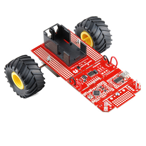
First off, a warning to those who may not be familiar with the ProtoSnap line -- don't break the board apart yet! The Minibot is designed to use the PCB as a structural element of the design and if you break it apart, well, that's not very structural, is it?
You'll need some basic soldering skills to assemble the kit, and basic Arduino programming skills to use it. Once you've assembled it (using the included direction booklet), you can program it to navigate mazes, avoid objects, or map a room. By adding some extra parts, you can make it a line follower, add remote control, or do just about anything else you can imagine!
What's included?
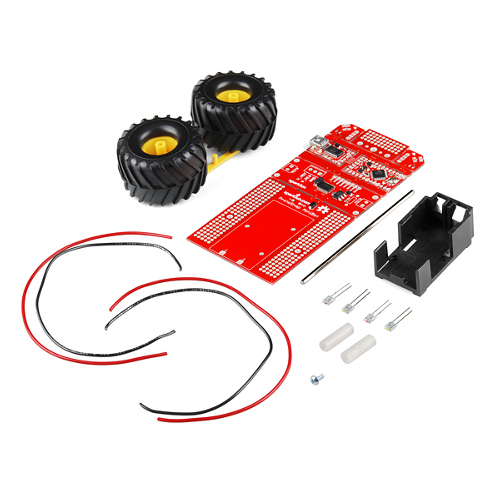
The Minibot kit comes with all the parts you need to build the robot:
- The ProtoSnap Minibot board
- A 9V battery holder (battery not included)
- 2 sets of infrared transmitter/receiver sensor pairs
- A Tamiya Twin Motor Gearbox
- Tamiya toy tires
- A standoff to keep the front edge from dragging
- Four wires for connecting the motors to the board
- An assembly guide with step-by-step instructions
You'll also need a few tools to finish the assembly:
- 9V battery
- A-to-mini B USB cable
- A soldering iron and solder
- A wire stripper
- A diagonal cutter or hobby knife for cutting apart the bits in the Tamiya kit
- A SparkFun screwdriver for assembling the Tamiya kit
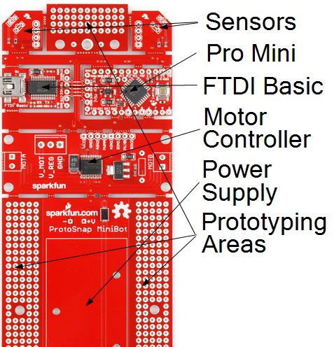
What's on the Minibot Board?
The Minibot board is broken into seven sections: a power/prototyping area, a motor driver, an Arduino Uno-compatible Pro Mini, an FTDI basic, two infrared reflective object detection sensor areas and another small prototyping area.
We'll start at the front of the board and work our way back. The object detection sensors are placed at a 45° angle to the direction of travel to provide directional object detection. The code loaded on the board is set to calibrate out ambient light, then look for objects too close to the front of the robot and attempt to avoid them by backing away and turning in the opposite direction. When assembled, the emitter sits flush with the board surface, while the receiver sits above and behind the emitter to avoid crosstalk between the two, which could affect results.
Between the two object detection sensors you'll find an additional prototyping area. Normally, the center hole is used for the standoff/screw combination which supports the front end; however the two holes to either side of that one are positioned to accept the Tamiya ball caster, which we sell. They can also be used with additional standoffs to mount downward-looking infrared sensors for line-following applications.
The next two sections are an Arduino Uno-compatible 5V Pro Mini and an FTDI Basic, which allow you to upload your code to the onboard Atmega328P at the higher speeds supported by the Optiboot bootloader. The chip is running at 5V with a 16MHz oscillator, and all of the standard pins you'd expect from a full-size Arduino board are pulled out, albeit in a smaller footprint. The connections to the motor controller, infrared LEDs and infrared sensors are pre-routed, so you don't have to make any of those connections on your own.
Behind that section is a motor driver based on the TB6612FNG chip. The motor drive voltage is preset to 4.5V; there is a spot for a through-hole resistor on the board which allows the user to adjust that voltage up or down for future applications. There are also .1" spaced headers for all of the relevant power and control signals, as well as .156" spaced holes for screw terminals (not included) for the motor outputs and power supply connections.
The last and largest section is the power supply and prototyping area. The battery cradle mounts to the pads provided here, as does the motor, and the row of pads closest to the battery along either side is tied to a single bus. These pads are perfect for attaching headers to provide tie points for external sensors, stepper motors, or other circuits you may want to add to the robot.
A quick trip through the Minibot code
You can download the full .ino file here.
Minibot ships with a very simple example program -- it calibrates the light sensors to ambient, then drives the robot forward until it detects an object. When an object is detected, the robot backs away from the object and turns to avoid running into it again, then starts off forward again.
The code is intended to provide an example of how to interface the motor driver and how to read the sensors, as well as to provide raw material to save end users' time in creating redefinitions for all of the pin connection signals. It is not intended to be a terribly useful application -- after all, where's the fun in that?
******************************************************************************/
// Application defines- these defines are used in the shipping application.

// Pins controlling the infrared prox sensors. The LED pins are outputs and can
//  be used to turn the transmitters on and off to avoid crosstalk. The BUMP
//  pins are analog inputs, and the more reflected light it detects, the lower
//  the signal at that pin will be. Note that the sensors do react to visible
//  light, too, so some sort of baseline calibration is recommended.
#define LEFT_LED     9
#define LEFT_BUMP    A1
#define RIGHT_LED    10
#define RIGHT_BUMP   A0

// Pins connected to the motor driver. The PWM pins control the speed, and the
//  other pins are used to select the current operation of the left/right
//  channels of the driver- forward, reverse, stopped, or brake.
#define LEFT_PWM     3
#define LEFT_1       4
#define LEFT_2       2
#define RIGHT_PWM    6
#define RIGHT_1      5
#define RIGHT_2      7

#define PING_DELAY 1   // Delay time between turning the LED on and checking
                       //  the sensor.
#define PING_RATE  100 // Delay in the main loop between polls of the sensors
                       //  for obstacle detection.
We start with the pin redefinitions. By redefining our pin numbers to something a little more user-friendly, we improve the readability of the code. I prefer "#define" to "const int" but either method will work. Next, I define a delay for the time between turning an LED on and scanning the input; that's not necessary but I've found (experimentally) that it does seem to improve behavior.
// Calibration variables and constants. We use two levels- detect and clear- to
//  provide for a little hysteresis. Excessive sensitivity is no good- we don't
//  want shadows to set it off, for instance. Also, we don't want the robot to
//  trip in and out of detection. Once an object is detected, we want to wait
//  a bit before declaring it cleared.

// The "detect" levels are the point at which the robot considers an obstacle to
//  have been found.
int rightDetectLevel = 0;
int leftDetectLevel = 0;

// The "clear" levels are the point at which the robot considers the sensor to
//  no longer be detecting an object.
int rightClearLevel = 0;
int leftClearLevel = 0;

// These are percentile changes in the level, not absolute changes. Thus, when
//  the light level deviates more that 20% from its normal "background" level,
//  we call that a "hit" and when it has returned to within 5% of its normal
//  level, we consider that to be clear.
#define LEFT_DETECT_OFFSET   20
#define RIGHT_DETECT_OFFSET  20
#define LEFT_CLEAR_OFFSET    5
#define RIGHT_CLEAR_OFFSET   5
We'll also set up some global variables for the detect and clear levels -- these are values populated during the calibration process. The idea of using a different level for detection than for clear is called "hysteresis." If we were to only back up enough to drop the light level to the point where it triggers an object detection, we may not go far enough to clear the object, and we'd trigger another detection right away upon resuming motion. The detect and clear offsets are the values used by the calibration function to determine the values for the detect and clear levels. I'll get to that in a moment.
// Setup runs at boot, every time. We use it to configure things- the pins,
//  calibration of the sensors, checking for whether or not to go into test
//  mode, etc.
void setup()
{
  Serial.begin(57600);  // This isn't actually used anywhere; it's here because
                        //  once you start modifying the code and need to add
                        //  print statements, you'll forget to put this back in.
  pinSetup();           // Configure the pins for the application. If we are in
                        //  test mode, this will also configure the pins needed
                        //  to support the addtional test functionality.
  driveStop();          // Just to be good citizens, make sure the motors aren't
                        //  going to just randomly start turning.
  sensorCal();          // testCode() will never return; we'll only execute this
                        //  if we are NOT in test mode. We will also only
                        //  proceed to loop() if we are not in test mode.
}
Now we're into the meat of the code: the setup() and loop() functions. You'll note that I abstracted most everything into a function call; that makes it easier to reuse my code in your applications later. setup() is pretty minimal. Enable the serial port for debugging, call a function, which configures the pins as inputs and outputs as necessary, make sure the motors are stopped, then calibrate the sensors. I'm going to skip pinSetup() altogether and driveStop() for now; let's take a look at how sensorCal() does its thing.
// This function calibrates out the local lighting conditions so the sensors can
//  detect objects without fancy shielding.
void sensorCal()
{
  // Start with a zero point...
  int leftCalLevel = 0;
  int rightCalLevel = 0;
  // ... then read the left sensor, with the LED on.
  digitalWrite(LEFT_LED, HIGH);
  digitalWrite(RIGHT_LED, LOW);
  delay(PING_DELAY);
  leftCalLevel = analogRead(LEFT_BUMP);
  // Now that we have a baseline for the light level with the LED on, but
  //  (hopefully) no object in front of the sensor, under the operating
  //  ambient light conditions, we can calculate the trip levels.
  // First, the detection level. We want to trigger on a level which is some
  //  percentage below "normal" (remembering that, as more light is reflected
  //  to the sensor, the analog value *falls*)...
  leftDetectLevel = int((float)leftCalLevel * (1- (.01 * LEFT_DETECT_OFFSET)));
  // ...then, establish the "clear" point- which is a point below the normal
  //  level, but above the detection point...
  leftClearLevel = int((float)leftCalLevel * (1- (.01 * LEFT_CLEAR_OFFSET)));
  // ...and then repeat for the other side.
  digitalWrite(LEFT_LED, LOW);
  digitalWrite(RIGHT_LED, HIGH);
  delay(PING_DELAY);
  rightCalLevel = analogRead(RIGHT_BUMP);
  // A note on syntax- by putting (float) in front of rightCalLevel, we direct
  //  the compiler to treat that value as a floating point number rather than
  //  as the int we declared it as above. This is called "typecasting" and is
  //  extremely powerful. We then use the int() function to convert the result
  //  back to an integer before storing it.
  rightDetectLevel = int((float)rightCalLevel * (1- (.01 * RIGHT_DETECT_OFFSET)));
  rightClearLevel = int((float)rightCalLevel * (1- (.01 * RIGHT_CLEAR_OFFSET)));
}
sensorCal() makes a couple of big assumptions: first, that the robot is in a relatively open area when it comes up from power off or reset, and second, that the ambient light will remain more or less the same during operation. Both of these are things that can be handled by more robust code; that's an exercise for the reader. The initial code simply turns on the LED, takes a reading of the light level, then sets the "detect" threshold to be a delta of 20 percent from that value and the "clear" threshold to be when the value returns to within 5 percent of the ambient level. It's worth noting at this point that as the reflected light level increases, the analog value on the pin actually DECREASES rather than the other way around. Thus, detection occurs at 80 percent of nominal, and clear occurs at 95 percent of nominal. A significant increase in ambient light level may cause spurious detections to be triggered.
// This is the standard application- the wall detecting-and-avoiding robot. It
//  only runs once the test code has successfully run once.
void loop()
{
  driveFwd(128);     // Start out by just driving forward.
  delay(PING_RATE);  // Limit the scan rate. This is pretty arbitrary- mostly,
                     //  it's important because if we add serial output code to
                     //  the loop at some point, we don't want it to dump out
                     //  data faster than we can watch it.

  // Check the left object sensor for any "hits".
  digitalWrite(LEFT_LED, HIGH);  // Turn on the left LED.
  digitalWrite(RIGHT_LED, LOW);  // Turn off the right LED.
  delay(PING_DELAY);   // Delay before checking the level. Probably not needed,
                       //  but we do it anyway because it doesn't hurt.
  // Remember, the analog voltage on the bump sensor is LOWER when more light
  //  is being detected, and more light will be detected when an object is close
  //  enough to reflect it. So, we check to see if the level is below the
  //  calibrated detection level.
  if (analogRead(LEFT_BUMP) <= leftDetectLevel)
  {
    // If we DO detect something...
    driveStop();  // ... stop the motors...
    delay(750);   // ... and let the wheels stop turning.
    // Then, while we are below the threshold that we calibrated for declaring
    //  our path clear of obstacles...
    while(analogRead(LEFT_BUMP) <= leftClearLevel)
    {
      // ...turn away from the obstacle we detected.
      leftFwd(128);
      rightRev(128);
    }
    // Once we've cleared the obstacle...
    delay(750);  // ...keep going for a little while to get well and truly
                 //  clear of the obstacle...
    driveFwd(128);  // ...then go back to driving forward.
  } // end left object detection check.

  // Once we've finished with the test for an obstacle on the left, check for
  //  one on the right. The process is EXACTLY the same.
  digitalWrite(LEFT_LED, LOW);
  digitalWrite(RIGHT_LED, HIGH);
  delay(PING_DELAY);
  if (analogRead(RIGHT_BUMP) <= rightDetectLevel)
  {
    driveStop();
    delay(750);
    while(analogRead(RIGHT_BUMP) <= rightClearLevel)
    {
      rightFwd(128);
      leftRev(128);
    }
    delay(750);
    driveFwd(128);
  } // end right object detection check.
} // end loop()
In the loop() code, we drive forward at half speed and check the sensors every 100ms or so (as defined by "PING_RATE").
By the precalibration of the light levels we've done, detecting a bump is as simple as checking to see if analogRead() returns a value below the established threshold. Then we turn away from the object until we get close to the ambient level.
// The left/right Rev/Fwd functions are set forth in the datasheet. Worth
//  noting- this is relative to the preferred assembly of the Minibot kit. If
//  you wire up your motors in another way, expect different results.
void leftRev(byte spd)
{
  digitalWrite(LEFT_1, HIGH);
  digitalWrite(LEFT_2, LOW);
  analogWrite(LEFT_PWM, spd);
}

void leftFwd(byte spd)
{
  digitalWrite(LEFT_1, LOW);
  digitalWrite(LEFT_2, HIGH);
  analogWrite(LEFT_PWM, spd);
}
Finally, a few words on the control methods for the motor driver. I've implemented a few functions: forward and reverse for left and right motors, forward and reverse for BOTH motors, and stop and brake functions for each motor and for both motors. The functions for both motors simply call the left and right versions; if one were to call leftFwd() after calling driveFwd(), that would have no impact on the operation of the right motor. Additionally, it is important to understand the difference between "stop" and "brake." Stop simply disconnects the drive from the motor -- the robot may continue to coast for some time. Brake actively connects the two poles of the motor to ground, effectively turning the motor into a generator with an extremely large load. The result is that the motors will come to a halt much more quickly.
Make it run!
Hopefully this is enough information to get you started playing with your new Minibot! Over the coming weeks we'll be adding more tutorials and information about hacking the Minibot for remote control, to add extra sensors, and more. We also plan to offer additional courses on Minibot through the education department, so keep your eyes open for that! We've given you the robot, now show us what you can do with it!
Can I use any arduino for this? I mean one bought from aliexpress or it needs to be original one?
someone (sparkfun gurus) could add code to show how this robot could follow lines too, please, with the sensors https://www.sparkfun.com/products/9453
Your tutorial is very userful but how can wee build this machine? Please add another example of this.
Yes, is very intresting this article. I will wait another tutorial to learn how you can build this machine !
Your tutorial is very userful add another example
My only problem with this is that I missed any reference to the necessity to first install the pro-micro addon to the arduino IDE before I could download to it. I re-installed the ftdi drivers and updated my arduino and it wasn't until I found that I couldn't upload to the other pro-micro I had in the box that I knew it wasn't me. In order to program this you'll need to download and install their new hardware definition that you can get from the pro-mini page https://www.sparkfun.com/products/11098
That should be step one in the tutorial people.
Oops, sorry I take that back. It's not a micro it's a mini. Though it's interesting that the micro download SAID it succeeded while the one meant for this fails. After following up on all the problems others had with getting this board to program I set it to an "UNO" and it is now accepting the programs just fine.
My only other comment would be that the voltage regulator on the motor controller board gave me a blister after only running the thing for a couple of minutes. OUCH that gets hot. Is it supposed to get that hot? I'm going to epoxy a heat sink on it before giving this to the kids to program.
Very interesting but can we somehow link the turning to a analog output pin and have steering precision?
This is great! Please add more tutorials and information.
May I recommend making a tutorial that shows EXACTLY how to get this thing running [ELI5 style].
Awesome stuff!
Yes, is very intresting this article