- Home
- Product Categories
- Connector Boards
- SparkFun USB Micro-B Plug Breakout

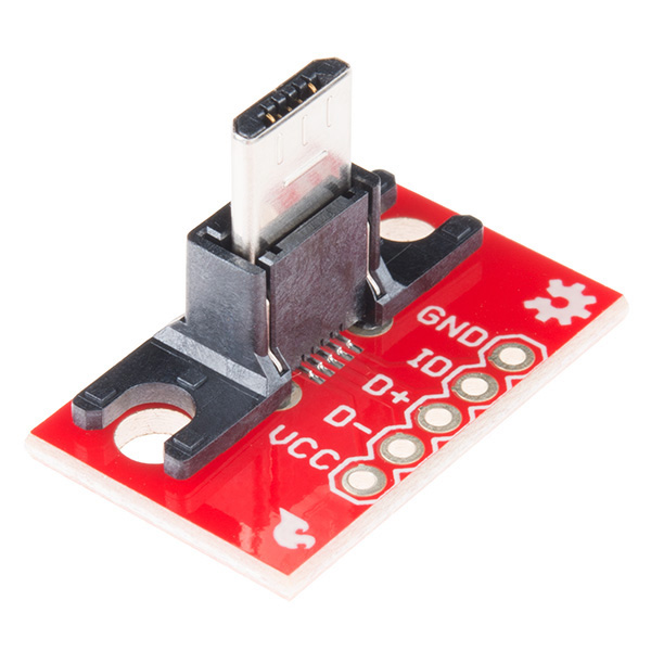
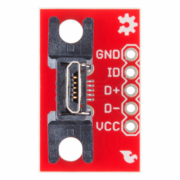
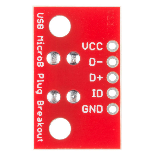
SparkFun USB Micro-B Plug Breakout
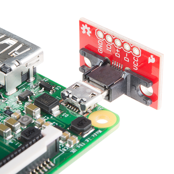
We have no idea what USB device you are hooking up to, but if you want to access the Micro-B port on something, you might want this. We broke out all five pins with a vertical Micro-B connector for your prototyping needs.
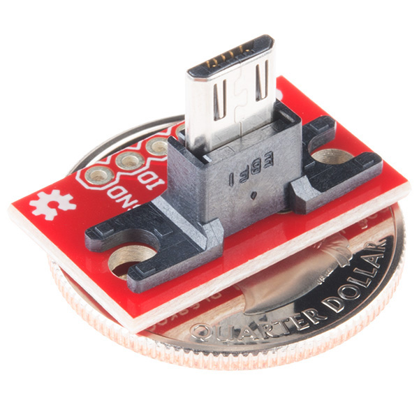
Dimensions: 23.54L x 14.75W x 14.65H mm
SparkFun USB Micro-B Plug Breakout Product Help and Resources
Connector Basics
January 18, 2013
Connectors are a major source of confusion for people just beginning electronics. The number of different options, terms, and names of connectors can make selecting one, or finding the one you need, daunting. This article will help you get a jump on the world of connectors.
Core Skill: Soldering
This skill defines how difficult the soldering is on a particular product. It might be a couple simple solder joints, or require special reflow tools.
Skill Level: Noob - Some basic soldering is required, but it is limited to a just a few pins, basic through-hole soldering, and couple (if any) polarized components. A basic soldering iron is all you should need.
See all skill levels
Comments
Looking for answers to technical questions?
We welcome your comments and suggestions below. However, if you are looking for solutions to technical questions please see our Technical Assistance page.
Customer Reviews
4.8 out of 5
Based on 12 ratings:
4 of 4 found this helpful:
Very useful for powering Raspberry Pis
This does just what is needed when having a Raspberry Pi board mounted inside a larger box along with a power supply and other electronics. Although the edge of the circuit board does interfere with the SD card on the Raspberry Pi B models, filing off a little at the edge of this makes it work fine. And as for the newer Raspberry Pi models where the power inlet has been moved around the corner next to the HDMI socket, there is no problem with this at all.
2 of 3 found this helpful:
Tablet / smartphone hacking essential
There's a lot that modern gadgets cram over the five pins on microUSB ports. USB device mode, of course. And charging too. USB OTG host sometimes. But sometimes hidden features can be unlocked when you put specific values of resistors between ID and ground. Depending on the device, some values can kick them into factory configuration and test modes, others will turn D+/- into audio line out signals, and some route a serial console RX/TX to D+/-.
This is the best tool I've used so far for hacking on microUSB ports, and was critical in discovering a way to a root process on the Nook Color among other tablet hacks. This is also handy for making quick measurements of USB VBUS current. You have the option to solder down pin headers for use with jumper wires, or solder in a cable for easier connection to a breadboard.
The lopsidedness can get in the way depending on the orientation of the microUSB socket on the device, but a book underneath to prop it off the table solves that easily.
If you're trying to open up the latest Android gadgets, this should be in your kit alongside a Bus Pirate.
0 of 2 found this helpful:
Excelente calidad
Un excelente conector y es genial que tenga el pin de ID, para hacking en smartphones sirve mucho
Solid as a rock
I used this and the female breakout board to make a custom tablet stand/dock. I was a bit rough with the parts during assembly and soldering since I was on a bit of a time crunch. This breakout is pretty solid and is going to last a long time in my application.
Raspberry Pi TNC-Pi Project
I needed an interface between the Raspberry Pi's micro USB port and an external USB port mounted on the wall of the project's metal enclosure. This breakout board was the perfect solution and made for efficient use of the enclosure volume.
Good USB MicroB Plug Breakout Board
Works great. Strong, since the mechanical attach to the board is "through hole" rather than surface mount.
Exactly What I Needed!
This board is great, easy to configure, pin out, and mount. And as bonus, the Sparkfun tech support is excellent. Will be purchasing several other breakout boards soon.
Makes something difficult easy
This little doodad takes something wicked hard (soldering tiny wires onto tiny pads embedded in plastic in the right order) and makes it dead easy.
Perfect for what I needed
This worked great for powering a Particle Electron board inside an enclosure since I just needed +5V and GND. Used an external 2.5 x 5.5 mm chassis mount power jack to get power from the outside, to this connector, to the Electron. Not enough clearance to chop a micro USB cable, so this was ideal.
Solved a power problem with Raspberry pi
Many if not most USB charger cables have such small wires there is a significant voltage drop by the time you get to the Raspberry pi computer board. The USB Micro B plug breakout board solved that problem by allowing use of a larger wire. Using the same 5 volt 5 amp power supply with my own wire I can now get full power to the pi circuit board.
0 of 1 found this helpful:
works great!!!!!
Bulding test equipment for cell phones, I need to order the female ones too.
I don't suppose there's a USB A male version of this board, or does anyone know if such a USB connector exists so I could create my own board? Thanks.
what are the overall dimension length width depth ? Assuming is a cube form?
Thanks!
Would this fit on a raspberry pi with the SD card installed? It seems like a bit of a tight fit...
The photo with measurements shows roughly 1cm from the edge of the connector to the edge of the board. With an SD card, my RPi has about 7 to 8mm of room between connector and card. It seems like you'd have to get handy with a Dremel-like tool to cut away some of the board on one side. It would be neat to have a slimmer breakout without the screw holes. It would be a great little board to build a power/reset switch on top of for the Raspberry Pi.
Fits perfectly with the microSD to SD card adapter I'm using. The small bevel in the SD card adapter is exactly the distance and shape to fit this breakout board. It's in direct contact which I would normally consider bad, but it actually seems to help in keeping the card from getting bumped around.
I purchased one a year or two ago and finally found it for use with my Pis. Both model A and B line up the same. I'm going to get a few more.
Crappy photos: http://imgur.com/a/L5z2y
Perfect for Nexus One mobile. Now i can make a cheap dock fo it :)
Was thinking of doing the same thing for my iphone 5 (before you tell me it wont fit, i have a mophie case)
How about selling just the plug?
We can consider it, but it's difficult to use, as it's a relatively tight-pitch SMD part.
Hey, you guys are the ones that taught me EagleCAD and tight pitch soldering! I'm sure there are people here who could get some use out of it. I actually jumpered to an unused pin on an LGA package last week with the soldering skills I learned here!
So don't think your customers couldn't use an eagle footprint and the raw part. ;)
-Taylor
You make a great point. I'll see what I can do, we have limited shelf space and can't have a spot for everything.
We probably taught you have to desolder too ;-) You can always remove it. Now THAT'S skill.
I personally would desolder it, except that I'm then not just paying for a connector, but also a coffee coaster. Another one. But hey! It's on the wish list. :)
Hi,
Do you have the eagle footprint of this connector??? I'm going to desolder a pair of this and solder it on a flexible pcb : D
Yep, any breakout board that we make will have the footprint in the SparkFun Eagle Library that we keep on github.
Great, all of you are awesome!!!
As a newly minted Eagle user, can you provide a link somewhere on the site (doesn't have to be here) for us to go to for that GITHUB? I'm loving the capability that Eagle brings to the table :)
Here you go. For any part that's in the Eagle library, there's a link at the top of the page (right under the SKU, next to RoHS, etc) that contains a link to the library. This one doesn't because it's an assembly.
I'm thinking about directly connecting the usb on these to tablets that I have in wall mounted at my house to control my home automation system, and then wiring the breakout power to a standard USB that plugs in a 24V DC power of ethernet to basically keep my tablets charged at all times.
I have all my AC wires and components in the standard metal or plastic gang boxes, so only the breakout and the wires soldered to i would live outside the gang box, behind the tablet and in a little cutout in the wall.
I know nobody can ensure anything is 100% safe and it seems like people are using these everywhere from the comments, but one link in the comments mentioned a fire hazard. Is there really a fire hazard with just 5V DC at 1-1.5AMPs charging a tablet? The wires to the breakout are soldered very cleanly with heat shrink and it seems fine to me - but am I completely crazy screwing mounting a tablet to the wall and direct connecting this to it? Not asking for 100% assurance just wondering if these is an obvious "Do Not Do".
I learned from the eagle schematic the the traces are 12 mil and by emaiing SparkFun that the external copper traces are 1oz. So the maximum current you can use this for is 970mA. That could be a problem if you intend to use this for some smartphones that charge at 1.8 Amps.
I wonder if that plastic comes off easily?
Not sure about easily, but from various photos (the datasheet for that connector isn't particularly clear on this) it does seem like it slides on top without much in the way of a snap fit type interlocking - so it should slide back off again as well. Failing that, a sword of exact zero should do the trick. Do keep in mind that the plastic is there for a reason.. remove it, and that plug's going to be a fair bit more frail, even with the mechanical supports on the actual plug itself.
Hi, it would be very helpful if this also came in versions compatible with the new iPhone and Samsung Galaxy plugs. Would you consider selling these versions as well?
Are there any of these boards with a female socket on them?
Yes. This one.
Would there be a chance of getting a side photo with the vertical dimensions? I'm building a panning camera controller to add motion to a Dropcam, it would be nice to know the vertical dimensions so I can design the enclosure.
Can we sell this with the male port vertically flush with the breakout board please? Peoples prototyping needs need this vertically flush with the pcb.
Any chance of a sheathed version? one you can make your own cables with? or a cable with all wires (including ID) or (this only really helps me) an USB OTG (USB host) cable where ID is shorted to ground
Thinner, or a flipped version would be helpful. It appears as the only reason for the width is to fit the silkscreened labels but you can put them on the back.
I need a really low profile (axially) connector and this works except it sticks out toward the back.
any chance of breaking out the shield contact as well? If you're abusing the USB standards, you can use this + the socket to make a really tiny and mechanically strong 6-contact connection.
Any plan to stock the horizontal version for cable making?
The jig is not working I plug it in my Samsung Galaxy i9000 and nothing happens.. What should I do?
http://factoidz.com/how-to-unbrick-your-samsung-vibrant-galaxy-s/
Put a 301k ohm resistor between pin 4 & 5.
You guys carry a female connector for use in making cables. I'd love to see this in a separate connector form factor so I could create some little heat shrink adapters.
The adapters on the market are scattershot WRT pins 4 and 5 being shorted.
What about a Vertical microB plug?
I need this ASAP.
I backordered it...How long would it take??
OK, I might be dumb or just tired, but how come the female Micro B breakout only has four pads and the male one has five? I'm not incredibly conversant with the Micro B spec; apologies.
any ETA on backorder status?
This is another life-saver (but I do not like the vertical orientation).<br />
<br />
I used it to build a jumper-configurable cable (from USB or battery to Nokia N900, plus jumper for host/client USB modes).<br />
<br />
Well, it doesn't appear very elegant when fitted to the N900 - perpendicular to it and with the larger part looking down, but it's so geeky... :-)
When you will have more units? I need at least twenty.
Perfect for manufacturing JIG's for Samsung Smartphones to call up various user modes, for example Car Docking mode, or Download Mode for when you brick your device. Many other modes exist and all that is needed is figuring out the resistance value between pins 4 and 5 to call up the function desired. Nice little board.
Great product. I build it in a car holder the Sony Erisson HCH-60. My HTC Desire fits perfect in it.
For charging in the car you need to connect the D+ and D- pins. See this post: http://forum.xda-developers.com/showthread.php?t=742706
Cool. Is there a vertical miniB on the way too?
I think this is the only vertical one we have so far.