- Home
- Product Categories
- Infrared
- SparkFun Photo Interrupter Breakout Board - GP1A57HRJ00F

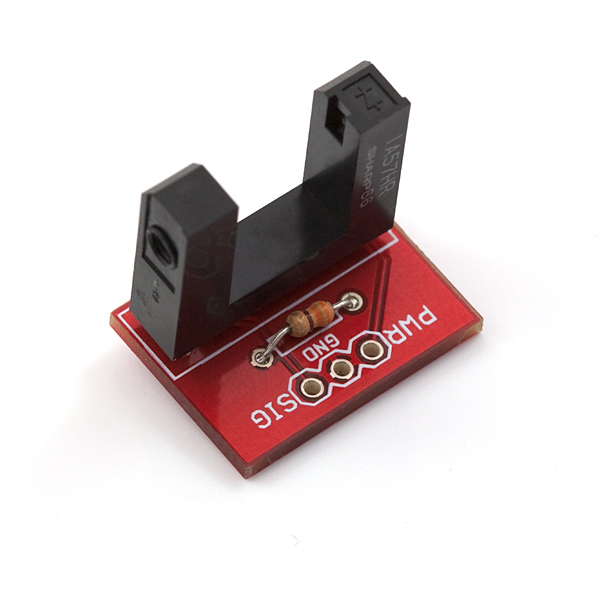
SparkFun Photo Interrupter Breakout Board - GP1A57HRJ00F
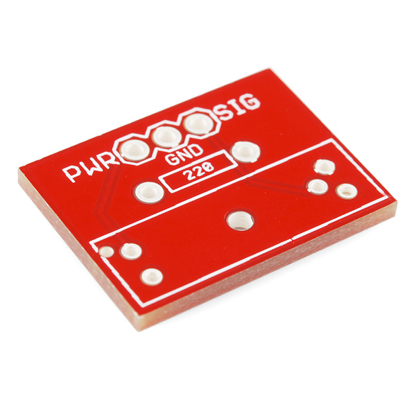
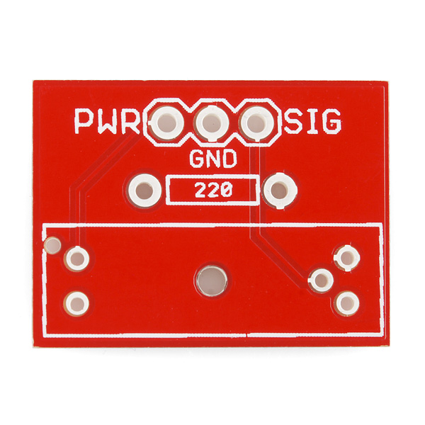
A simple breakout PCB for the GP1A57HR photo interrupter (also known as a photogate, photodiode, or phototransistor). This PCB has three connections for PWR, GND, and Signal.
When the gate is clear, SIG will be high (>4.9V). When the gate is blocked by a finger, writing utensil, food pellet, or anything else - SIG will go low (<0.4V).
Assembled picture is for reference only, board comes bare; photo interrupter and the 220Ω (330Ω, works as well) current limiting resistor are listed below.
- Schematic
- Eagle Files
- GitHub (Design Files)
SparkFun Photo Interrupter Breakout Board - GP1A57HRJ00F Product Help and Resources
Core Skill: Soldering
This skill defines how difficult the soldering is on a particular product. It might be a couple simple solder joints, or require special reflow tools.
Skill Level: Noob - Some basic soldering is required, but it is limited to a just a few pins, basic through-hole soldering, and couple (if any) polarized components. A basic soldering iron is all you should need.
See all skill levels
Comments
Looking for answers to technical questions?
We welcome your comments and suggestions below. However, if you are looking for solutions to technical questions please see our Technical Assistance page.
Customer Reviews
4.5 out of 5
Based on 4 ratings:
1 of 1 found this helpful:
Nearly perfect
This little board makes interfacing the Photo Interrupter a breeze. My only wish would be for some sort of mounting holes.
I'm going to be using this in a Lunar Clock, to detect the starting-point slot in a large wheel. Its mounting needs something like screw holes so I could fasten it to a supporting (insulated) bar. It would be great if that mounting didn't increase the width of the sensor - I'm trying to minimize the space between the wheel and the outside of the clock. A pair of small bolt holes near the P and S of PWR and SIG would be perfect.
P.S., I used a 3-pin header soldered so the pins are below the board (the opposite side of the Photo Interrupter part). That made it easy to insert it into a breadboard to try out the code and electronics.
Good product
Bought 8 of these for a project. All worked.
It works!
Works exactly like you’d expect, easy to set up and program on a raspberry pi. Would be nice if it had mounting holes.
Perfect for my application
Been using them for years with the photo interrupters for homing engraving machine axis. They rarely go bad, and work perfectly!
It turns out I got away with drilling mounting holes into the board, on the corners near the "PWR" and "SIG" labels. Photos at https://needhamia.com/?p=458. Note: doing that will short the mounting hardware to the ground plane of the board (which seems harmless to me).
Many people have asked for this breakout board to include mounting holes. I had a need for that as well, so designed a replacement and had them made on BatchPCB. Just got the boards yesterday so did not have a chance to test them yet. The two screw holes line up perfectly to fit on a MicroRax beam profile.
http://www.batchpcb.com/product_info.php?products_id=73267&check=f04f2fd9f7982d658c6d4e73e484ce9c
Picture: http://twitter.com/#!/galaxiecruzin/status/147106128596176897 Your welcome!
Link is not working can this mount still be purchased?
It would be nice if these boards had at least two holes for mounting the board to a surface. This board configuration requires the user to make a custom bracket or use double sided tape or bubblegum to mount it....
And also, why would you continue to sell a product that you know is not up to par? This board is missing the hole for the alignment pin. Throw them in the garbage. I see that the qty in stock is pretty low now. So you have almost gotten all 540 of your known crap boards out. Good job. Put a disclaimer in the description for Pete's sake stating that you have to cut parts of your sensor off to use this board as intended.
My output has some ringing in it. Seems like the Schmitt trigger is glitching. Do you think a bypass cap would help things? Is there a reason there isn't one on the breakout board?
If you go to the data sheet for the photo-interrupter, they recommend putting a 103 capacitor across the power supply and the ground. Also read my post about my suspicion of the current limiting in the comments on the photo-interrupter device itself. You may need to add a transistor circuit on the output in order to drive things that need current like LEDs. If you hook it up without the the SparkFun board, make sure you pay attention to the ~47 ohm series resistor on the infrared LED that is shown in the datasheet for the device under the timing test. I think it might be built into the Sparkfun board, but not in the device itself. It sizzled one photo-interrupter when I forgot to include it.
Can I get an eagle schematic file for this? Thanks
We will be posting the Eagle files momentarily. You can find them here until then.
will 5V be good to power this device
Will this be back in stock soon?
I want to use this item connected to a mainboard with a flat cable. Anyone know the spacing of the connector holes? Suggestions on flat cable connector would be greatly appreciated.
Connector holes are 0.1" spacing
I am happy to report that the versions of this board I just received have holes for alignment pegs, and the sensors pop in without modification.
The lack of mounting holes is a serious problem, though.
RE: It would be nice if these boards had at least two holes for mounting the board to a surface.
I second that. Don't really want breakouts just hanging around esp for mounting the sensor where I am trying to detect a physical stopping point.
HI. Is this possible to Do the opposoit with this breakout Board ?
HighVoltage (80V) > Photo Interrupt > Arduino input (5V)
Agree! A hole for the locator lug. Plus, you said 220Ohm on silk layer but have a 330Ohm resistor on the assembled picture.
Yeah, various resistor values work. Hence the 330ohm comment. Use whatever works best for your application. I said 220 because it worked when I was doing the layout for the PCB.
The locator plug was also my mistake. The new ones should be on the storefront once the remaining 540 of these PCBs sell...this could take a while.
Perhaps for the next version you could drill a hole for the locator lug.
Hmm, unless I have done some completely faulty assembly, could your description be incorrect? My assembled breakout with interrupter and resistor looks just like the one depicted, yet SIG is high when the gate is clear, and goes low when the gate is blocked.
Good catch, d3x. The description was backwards; fixed now. Thanks!