- Home
- Product Categories
- Arduino Shields
- SparkFun WiFly Shield

SparkFun WiFly Shield
This new version breaks out the PI09, FORCE WAKE, and the hardware reset lines. It also has a different crystal and uses the RN-131C.
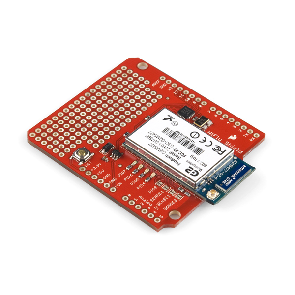
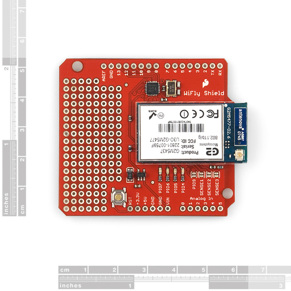
The WiFly Shield equips your Arduino the ability to connect to 802.11b/g wireless networks. The featured components of the shield are a Roving Network's RN-131C wireless module and an SC16IS750 SPI-to-UART chip. The SPI-to-UART bridge is used to allow for faster transmission speed and to free up the Arduino's UART.
Power is taken from the Vin pin of your Arduino, regulated to 3.3V, and provided to both the RN-131C and the SC16IS750. You'll communicate with the WiFly Shield over SPI using Arduino digital pins 10-13 (CS, MOSI, MISO, SCLK respectively).
The shield includes the RN-131C, SC16IS750 and their supporting components. The shield also provides a small prototyping area, with 0.1" spaced holes. Headers are not soldered on, we recommend the 6 and 8-pin stackable headers.
- Schematic
- Eagle Files
- Datasheet (RN-131C)
- WiFly User's Guide
- SC16IS750 Datasheet
- Hookup Guide
- Talking Wireless Server Tutorial
- WiFly Troubleshooting
- Wireless Water Sensor Project
- GitHub (Design Files & Example Code)
- GitHub (Library)
SparkFun WiFly Shield Product Help and Resources
Core Skill: Soldering
This skill defines how difficult the soldering is on a particular product. It might be a couple simple solder joints, or require special reflow tools.
Skill Level: Rookie - The number of pins increases, and you will have to determine polarity of components and some of the components might be a bit trickier or close together. You might need solder wick or flux.
See all skill levels
Core Skill: Programming
If a board needs code or communicates somehow, you're going to need to know how to program or interface with it. The programming skill is all about communication and code.
Skill Level: Competent - The toolchain for programming is a bit more complex and will examples may not be explicitly provided for you. You will be required to have a fundamental knowledge of programming and be required to provide your own code. You may need to modify existing libraries or code to work with your specific hardware. Sensor and hardware interfaces will be SPI or I2C.
See all skill levels
Core Skill: Electrical Prototyping
If it requires power, you need to know how much, what all the pins do, and how to hook it up. You may need to reference datasheets, schematics, and know the ins and outs of electronics.
Skill Level: Rookie - You may be required to know a bit more about the component, such as orientation, or how to hook it up, in addition to power requirements. You will need to understand polarized components.
See all skill levels
Comments
Looking for answers to technical questions?
We welcome your comments and suggestions below. However, if you are looking for solutions to technical questions please see our Technical Assistance page.
Customer Reviews
No reviews yet.
Is there any explanation as to why this product was retired? Or it was just because? I have one and it works great. I came here to get another one and it's retired. Any comments?
I am new to arduino wifi. I bought this module and planned to integrate it with the weather shield. However, I realized it has the original non R3 layout! I cannot put the weather shield on top of the wifely shield! Unless I cut the legs of the additional two legs on the weather shield R3 layout. But doesn't that defeat the purpose of shields if I want to put something more in between?
Why is the wifi shield esp8266 only $14 dollars while it has R3 layout and can connect to wireless n? While this $69 wifly shield does not? I am new to wireless connectivity so please correct me as logic tells me I may not be correct here.
Three things required to make the library work in Arduino 1.01 IDE. I am using arduino uno r3 stacked with this wifly shield...
1) Understand the program carefully. Library is good but has few flaws, might need to re program for added functionality.. Im adding UDP packets looking at other libraries. should not be too hard.... Id advise to follow the speaker jet tutorial and look at water sensor project...
2) Change the struct for SPI configuration as stated in tutorial comments. So will require to change the header file conf... struct SPI_UART_cfg SPI_Uart_config = {0x50,0x00,0x03,0x10};
to...
struct SPI_UART_cfg SPI_Uart_config = {0x60,0x00,0x03,0x10}; if doing the tutorial for speak jet...
In the library the struct changes in SpiUart.cpp and only has two bytes and need to config other bits in the header file
change it to from something else to
struct SPI_UART_cfg SPI_Uart_config = { 0x03, 0x10 };
3) Try to run all the library examples.. The problem I got stuck with was with the server example. So I developed my own server using the tutorial and that seemed to work however the example server did not . Found that it was just a delay of 200 ms required in void loop() function at start... there should be delay just before server is checked again..
delay(200); WiFlyClient client = server.available();
That should make the library run ..
hope it helps and there is my weekend...
Good day Member #320550, I'm Yannick, third year student at the faculty of electrical engineering at TUT (www.tut.ac.za) here in South Africa. I'm working on a project based on creating a wireless network using arduino uno-R3 and the breakout board WiFly-Shield 2.21 RN-131C from sparkfun... I'm using arduino 1.0.5 skecth, and still testing my shield to see if it responds as expected: like receiving "CMD" after sending "$$$". But I do not receive such response from it, I'm busy working on it hoping to figure it out soon; meantime I'd like you to please check the following code of mine I used to do it, hoping you would give me a hint to solve it.... Thanks, Kind regards.
" /* This code tests my Sparkfun WiFly-Shield */
// headers files or librairies #include
// Declare/Initialize Vars. int rx_in = 0, tx_out = 1, cnt = 0; char wif_dat[5];
// Functions prototypes
// set up function, run once when program starts void setup() { //set i/o pinMode(rx_in,INPUT); pinMode(tx_out,OUTPUT); //Initialize serial com. port at 9600 bps Serial.begin(9600); // Serial.print("set uart baudrate 9600"); }
//loop function, run infinitely after program starts void loop() { //Set shield in command mode //Serial.println("$$$"); delay(200); //wait till data arrive while( Serial.available() > 0 ) { wif_dat[cnt] = Serial.read(); cnt++; }
wif_dat[cnt] = '\0'; Serial.println(wif_dat); }
//Functions "
Thank you, your tip for the delay(200) changed my WiFly shield from a non-responsive piece of expensive junk back into a valuable piece of kit. I am very grateful.
42$ for a shield (2$ for headers), I can buy 2x Arduino Pro's for that.
You can buy 200 Arduinos and still not be able to connect to wi-fi ;-)
lol
$42?
This costs $90.
Look at the price of the WiFly module alone, then subtract it's price from the price of this shield, that's what he's talking about.
$90? This is $69.95.
We dropped the price in the past year
That makes sense. My mistake.
I made a small robot with the WiFly.
Check my video!
http://www.youtube.com/watch?v=tjR969Vp0Cw
I am using the Wifly shield with an Arduino Uno R3, using the latest Roving firmware in the WiFly module. The sketch works fine as long as I'm connected to the computer via USB, but not if I run the Uno from a wall-wart using the barrel power connector. Note that the Uno/WiFly does not send any data to the host computer, it's only getting power from the USB connection.
In monitoring the SPI pins, I see that at least the SCLK and SS signals disappears as soon as the first character is received over the WiFly connection. However, if I reset the Uno (hit the reset pushbutton) without pulling power, then everything works fine after that. The SPI signals are correct, and dont' go away.
I've tried slowing down the reset pins on both the Arduino and WiFly SPI UART with caps, using Spi_Serial.begin() more than once, various delays in setup (in case the power is coming on too fast), etc, but can't find the problem. I've tried various wall-warts and power supplies to make sure that the voltage to the Arduino is fine.
Has anyone else run into this? Where the Arduino/WiFly works fine from USB, but not from external power?
Please update the link to the Experimental WiFly Arduino Library to the latest alpha 2 release. The currently linked library is the old version won't work with the latest revision of the shield.
Or maybe also to the github repository.
Does anyone succeeded in modifying the library for use with the Maple?
Alas not - despite the claims on the LeafLabs site.
I've been trying to do this for a while, have you had any luck?
(sorry for the formatting, don't know how to post properly on this forum) Yep, i finally sorted it out ... Note that the following is for the SPI1 port, but can be easily modified to match the SPI2 or SPI3 port if available ...
In "_spi.h", include the "stdint.h" and remove the "pins_arduino.h"
In "_spi.c", include headers "_Spi.h", "libmaple.h", "spi.h", "wirish.h"
deselect(); }
Can it use as sniffer? Can it recive all the packets in the network?
Is it possible to use this with an SD card shield? I'm getting the impression they use mostly the same pins... Is there some other solution where I can add an SD card for storage and WiFi to the same Arduino?
Yes, it's possible to use this shield with the MicroSD shield. I know because I've done it. :)
The pins the two shields can and do share are used for SPI communication but they still have separate "chip select" pins which means the two shields can co-exist.
Please contact techsupport@sparkfun.com, they can help you with technical questions.
I'm having a lot of trouble setting this up. When following the hookup instructions I get to the CMD prompt in the SpiUART Terminal. When I try to scan or join I get the following response:
wifly-GSX Ver 4.00.1, Apr 19 2013 11:48:28 on RN-131MAC Addr=00:06:66:31:d9:90READY
I tried entering my wlan auth, wlan phrase through he terminal but when I try to join through the terminal I get the same response.
Any ideas?
I cant get this thing to work. When going through the hook-up guide, I get to the CMD prompt in the SpiUART Terminal. When I scan for net works I got the following response:
wifly-GSX Ver 4.00.1, Apr 19 2013 11:48:28 on RN-131 MAC Addr=00:06:66:34:5c:18 READY I try to set the wlan auth and wlan phrase and get the appropriate response (AOK) but when I try to join SSID I get the same response:
wifly-GSX Ver 4.00.1, Apr 19 2013 11:48:28 on RN-131 MAC Addr=00:06:66:34:5c:18 READY
Any ideas?
Now that I've bought one of these, I see a lot of the comments are quite old and there isn't much activity in the development area. It's not awful so far (I pinged google!) but is there a real advantage of this product over the much cheaper alternatives? I have a sinking feeling that development is sorta dead on this product, and other cheaper and more popular products are getting the love and attention these days. I'm worried about getting a few basic features implemented and then hitting a brick wall or two.
Is this more reliable than the CC3000 shield? With the CC3000 I have to run a timeout loop and do a hard reboot with an NFET about every 6-8 hours of continuous operation as it drops the connection and goes belly-up. I'd like a wireless module that can stay connect to the access point for more than a few hours without having to be power cycled... like maybe a month or two?
So far, I'm not impressed. Firmware version 4.00.1. Running the latest library from github. For any but the most simple examples, this will not hold a connection long enough to respond to a client. The LED example in the tutorial disconnects before it can finish parsing a single POST. The very simple example, WiFlyWebserver works.
I should add, as reported in some of the other posts, when it locks up, the green led goes solid. Any clues?
How do i wake the wifly shield with my arduino uno? i have been looking for examples so far i can only find them the other way around with the uno being woke by the shield. all help appreciated.
Could anyone provide a circuit diagram of connecting an Arduino Uno, Arduino Motorshield and the Sparkfun WiFly Shield?
What version of the firmware does this ship with nowadays?
Hi, can I attach this module to a Arduino Pro Mini?
welcome everyone how can connect wifly RN-131C to android via arduino UNO because my android device can't find wifly network signal to make connect and I tried to connect many devices to wifly but i can't ? Is wifly RN-131C can made connect to android device or not ? please help
To anyone wondering about the voltage regulator on the board, I inquired with SparkFun and received the following information:
The shield uses a MIC5205 which can handle up to 150mA with an operating range up to 16V. http://www.micrel.com/_PDF/mic5205.pdf
I am using the RN-171 on the Seeed Wifly shield but this device looks very similar. I have not used AdHoc mode - the easiest way (on the RN-171, but this one looks identical) is to set up the unit via the UART to associate with your access point and get an IP address via DHCP, then just telnet to port 2000 on the module. When not in command mode, the device will just stream serial IO back and forth between a client TCP connection (like telnet, but any TCPIP client will work) and the UART. You don't need a special library, just Serial or SoftwareSerial.
Since the device has a full-TCPIP stack, you can do things like read the module's time, which can be set via NTP, and use it accurately sync your Arduino to network time. The RN-171 also broadcasts a UDP packet periodically that has the time, RSSI, GPIO/sensor pin status, etc, you can read this from any computer on your network.
So it's pricey but has a lot of capabilities. For cheap peer to peer communications, I'd spec a 433MHz or similar module and user VirtualWire instead, or Xbee, etc.
OK this thing is making me crazy. It doesn't seem to matter what library I use the end result is the same. WiFly gets an address, that I can ping, but no response from the web server in a browser. Green light goes from flashing to steady. I read this problem in earlier versions and the recommended fix is in server.cpp but this happens every time even with the most recent library that I can find. The Ethernet sketch works fine but not the WiFly sketch.
Some details; Using Arduino 1.5.2, Uno R3, WiFly shield Rev3, WiFly_Shield_Master library from GitHub (modified 20 days ago) and trying to run the Webserver example. I have tried five different libraries and modified the Ethernet sketch to get the same result. HELP!
I bought this shield and connected it to my Arduino R3. I tried almost all the libraries. However, the SPIuart cannot not work correctly . Even I enter the command mode, and run the "scan" the output is mess. Then I soldered two wires to connect the UART port of RN-131C to the digital pin 2 and 3 of Arduino and use the softwareSerial to talk to the shield. The output is good. I am wondering whether anybody else have ever got this kind of problem. If so, would you please tell me the solution? I really want to use the library for the shield, or I have to struggle with the SoftwareSerial.
Anybody here?
Sorry about that delay. Please contact techsupport@ with your questions. They will be able to assist you better than we can in the comments.
can someone explain why the update doesn't work for me? I am connecting RN171 to my router (BTW how to be sure it is connected?) When doing all the FTP UPDATE stuff I get at the end 2.32> FTP connecting to 0.0.0.0 FTP timeout=2 IF=UP DHCP=ON IP=169.254.187.231:2000 NM=255.255.0.0 GW=0.0.0.0 Listen on 2000
And it doesn't seems to update anything, tried reboot, factory R nothing works? Why? Thanks, Roee
is this compatible with Arduino UNO/Duemilanove?
I am trying to use the WiFly shield and the TLC5940 shield. The issue is that the LEDs that are connected to the the TLC5940 channels turn on with the LEDs of the WiFly blink. Any help is appreciated.
DELETE
The link to Experimental WiFly Library (Arduino 1.0) does not work. Anyone know where I can download the most up to date library from?
The ones I get are for older versions and keep giving byte errors.
Is this compatible with Arduino DUE in terms of voltage levels (SPI)??
I tested this shield with the Due and it worked fine. What you will need to do is to make a few fixes here and there in the library code as it won't work as is in the Due.
Do you have any additional information you can provide? I'm trying to use this WiFly shield (with RN-131C) with the Due (R3). I'm still a newb, but as far as I can tell, three of the SPI pins have moved to where ICSP pins were on the Uno. That is, the WiFly is expecting SPI on pins 10-13, and can still use 10 as CS, but MOSI, MISO and SCLK have moved. I assumed this means I need to jump some wires over there (and solder them directly, or at least get some additional connectors to be nicer), but can the SPI be reconfigured in the WiFly library to use pins 10-13 again? Or is it something else?
Is this shield compatible with the Arduino Due? Thanks.
Anyone know what regulator is on the board, or at least its input voltage range. I'd like to stack this with the CAN shield and power it off the car's 12-14V. I powered it with 15V on my bench, and it got very warm in just a moment, so we can pretty much rule out it being powered off the vehicle battery. I guess I could pop the regulator off and run 3.3V from the arduino due's regulator, which is supposed to be happy up to 12V (and probably OK higher). It did not get warm with 15V input (at least not appreciably).
For anyone thinking of buying this I would suggest not to. Very temperamental, pretty impossible to get working, generally just a pain in the arse.
I have a very detailed step-by-step tutorial for creating a remote wifi sensor with this board here: http://www.oneassetplace.com/pages/BuildWifiSensorArduino I hope it helps someone!
Does anybody know of a currently verified working WebClient example + IDE configuration? I'm trying to use the WiFly shield with an Uno R3. I've tried Arduino 1.003, 1.0 and 0023. It hangs at WiFly.begin();
This is using WPA2.
Does any one know why the WiFly would halt on "client.println("? I tried to tweet via wifi and it will establish a connection to my network, it will connect to the client and then halt on "client.println". So I tried the example provided by the WiFly Library (Arduino 1.0), "WiFly_WebClient_Faster" and found the exact same result.
Do I need to change firmware update on the WiFly or something? I'm not sure why its doing this.
PLEASE HELP
Is this compatible with the arduino romeo? If so, is it just a case of mounting it right on top or is there additional things to consider like jumper pins or anything. I cant seem to get mine to work. I assumed that i would get one of the power led s to light as soon as i plugged it in but nothing is lighting. I also cannot communicate with the device via teraterm. I borrowed this device off a friend so it could possibly have malfunctioned.
Why I can not have white space in the SSID nor in the password? :( does anybody have a work around for this?
iArd connect arduino to iPhone via ethernet, WiFi and WiFly shield! Available on app store! Visit http://nkcorporation.altervista.org
So is this 20 dollars price drop permanent or what?
Yes, we don't do temporary sales, but sometimes we do have to adjust our prices to stay competitive.
Just a comment... if the internal function reboot() which is called from WiFly.begin() fails the library authors decided to just loop infinitely with a while (1);
Might I suggest returning an error condition to the user instead?
Hello! I would like to use AC adapter with Arduino Uno + Wifly Shield. When I connect AC adapter to Arduino Uno, Vin gives 8V output. Wifly shield requires 3.3V. Does that shield regulate voltage to 3.3V? That's what is in description, but I want to be 100% sure. Thanks...
is this comptible with Microchip PIC18F4550??? sorry to ask but I’m new to electronics ;P
http://www.microchip.com/forums/m534585.aspx
hope this answers.. the concept is the same if u use arduino or other microcontroller using SPI... wikipedia spi and i2c to get basic info. and look at library and try to figure out the way from there
Anyone still using this board. I am noticing weird character corruption coming off uart. Sometimes an 'á' will show up randomly, or the uppercase version. anyone else seeing this?
nah it works fine. update firmware and try. likewise also do hardware reset
What does it mean when the PIO4 led is solid green? It seems to be happening somewhat randomly (during activity) and renders the unit unresponsive until rebooting. Something I can code in to prevent it?
Hi, I'm experiencing the same behavior. Did you figure out the solution?
Arduino ide 1.0.1 terminal tool which works for my uno r3, just because I was unable to find one easily.
Does Sparkfun really only sell a $90 WiFi shield? Honestly, there should be a sub $20 option available. For crying out loud, cellular shields are cheaper than this. I don't even.
Find us a sub $5 Wifi module and we'll consider it. Don't forget, we still have to pay our engineers to design the board, our production guys to build it, our shippers to pack it, not to mention the actual board and all the other components. Wifi modules unfortunately are not cheap! But cheer up, we did lower the price from $90 to $70.
I must not understand what's involved. I see USB dongles with WiFi for like $5 retail, pocket routers for ~$15 on eBay...I take it those modules are wildly different?
Those computer peripherals are $5 because they're not a whole lot more than radios; the complex network processing is handled in the operating system of the host computer. The WiFi devices we carry are meant to connect to small processors with limited resources; the modules handle all the layers of network processing internally, and present only the final data via simple serial interface to the microcontroller. That's a lot of hardware and firmware, and because the larger market is for those $5 modules that do require a full computer, we don't see quite the economies of scale that those parts enjoy.
I have a problem. It seems my code/wifly shield simply stops reacting. It sends to a Google Spreadsheet but after a few sends it totally freezes and no more sends are made.
The code can be seen here: http://arduino.cc/forum/index.php/topic,108646.0.html
Any ideas?
Is that card is compatible with all Arduino cards including the Arduino Duemilanove? Arduino's UART means that? Sorry i'm a french novice ;)
how can i use it with arduino Uno and is there any changes in wifly library ??? thaaaanks in advance
What is the host name of this devie? I thought its WiFly-GSX but when I try pinging using its name i get this error below.
C:\Users\User>ping WiFly-GSX Ping request could not find host WiFly-GSX. Please check the name and try again.
I found a way of getting its host name but am not getting any result. This is shown below.
C:\Users\User>tracert 172.16.96.186
Tracing route to 172.16.96.186 over a maximum of 30 hops
1 2 ms 2 ms 1 ms 172.16.96.186
Trace complete.
Please help!!!...
this tutorial is for beginners to the wifly shield , it have a complete guide and easy http://mgisolutions.blogspot.com/2012/05/arduino-wifly-shield-tutorial.html
I've been looking for a WiShield replacement since I can't seem to find them online anymore. It took me a long time to figure the WiShield 2.0 out... how similar is this to the WiShield 2.0? My code if you need it can be found here: http://goo.gl/yHuLp
Hey all,
Concerning UDP communication using the Wifly shield: I just finished putting together the first phase of a project I've been working on (Arduino Wifly Mini, controlled by G27 steering wheel with force feedback.) It relies on two-way UDP communication between Processing and the Wifly. A couple people have told me they found the write-up useful, so if you're not afraid of beastly raw code... here's the link:
http://www.blairkelly.ca/2012/04/20/arduino-wifly-mini/
Hope it helps if you need it.
Best regards,
BK
Wow, great write up! I enjoyed your video. I'm a novice, but it was understandable.
Sharing SPI (WAV Shield + MEGA +WiFly) - WiFly/WAV cable select pins
I'm having issues using this shield w the Adafruit WAV shield which also uses SPI for the SD card reader.
Using separate cable select pins for the WAV shield (pin 33) and WiFly (53)...I can toggle from WAV shield to WiFly shield but I can't toggle back to the WAV shield...If I initialize the WiFly shield first, I can't toggle to the WAV shield.
//this enables the cable selection pin for WiFly shield void enableWiFlyShield() { digitalWrite(SSWIFLY, LOW); digitalWrite(SSWAV, HIGH); }
//this enables the cable selection pin for WAV shield void enableWAVShield() { digitalWrite(SSWIFLY, HIGH); digitalWrite(SSWAV, LOW); }
See my thread with specs and setup here: http://arduino.cc/forum/index.php/topic,101660.0.html
Has anyone successfully deselected the WiFly in order to talk to another SPI device?
I think it is best to keep the cs high (for both devices) and only drive low when you need to access the device. At least for the wifly shield, each register read or write on the uart should have a toggle of the cs.
This is my setup for the two shields.
And I toggle them with the code above, setting the active devices cable select pin to low and non active cable select pin to high.
Has anyone had success using this shield with multiple SPI devices?
I wonder if this my issue is related to similar SPI issues with the ethernet shield:
http://www.arduino.cc/cgi-bin/yabb2/YaBB.pl?num=1248045864
I have a feeling this shield isn't gracefully disconnecting from the SPI bus. If anyone has successfully used this shield with another SPI device, let me know!
This works great with my maple, would like to see pins brought out for status of association, connection, and command mode, as well as a pin to put it into command mode. Using the interrupt was difficult because you don't know much about the state of the device. I am using it at spi of 4.5Mhz and uart at 921600 with hardware flow control, that seems pretty solid. Programming the uart seemed a bit tricky because of the way you need to access some of the registers, but it is nice to have the interface so you can burst out the incoming characters.
can anyone please provide me the complete code, library and instructions for configuring the wifly.
I have posted a three-part blog series here that should help: http://www.cc-logic.com/blog/posts/physical-computing-part-1-of-3-getting-wifi-working Best of luck!
It appears there is no provided code that will fetch the RTC Real Time Clock's time to synchronize with the system clock. I decided to write one. You can find my code at the following forum thread:
http://forum.sparkfun.com/viewtopic.php?f=8&t=31765
I use the wifly shield with an Uno R3 and with Arduino 1.0
I just got this sensor in and saw mention elsewhere that the wifly only supports one simultaneous connection?! The ethernet shield supports 4.. is it true this product only supports one connection at a time????
It does appear that there is a one connection limit. I'm disappointed this wasn't made more clear in the product description. I may have purchased differently had I known this in advance.
Here is my second question since my previous comment was cut short. Why doesn't the newest Wifly library, WiFly-20101217-alpha-2 compile immediately "straight out of the box"? I tried to compile Wifly_WebServer.pde but get various errors such as 'SpiUartDevice' does not name a type.
I think the issue here might be that you are working off a newer version of the IDE. What version are you working on? I know 1.0 fails to compile it completely, and I revised back to 021
I have just bought the WiFly shield and got it working (more or less) with my Arduino Uno using some of the software provided by Chris Taylor. Now I have two questions that I would be grateful for help with: 1) In the definitions of the addresses of the SC161S750 uart bridge, why are they left-shifted in the #define section e.g. #define LSR 0x05 ?
So I just got this thing.. software is horrid.. Alpha 1, Alpha 2? OK... Stacked it on my UNO and hooked it up to win/mac serial programs but nothing I do/follow can get this thing into CMD mode. I've spent HOURS trying to do this.. So very disappointed!
What terminal program are you using? I use CoolTerm and it works. The Arduino Serial Monitor does not work. Try the WiFly Autoconnect Example first and see if that works - it starts in CMD mode.
Dear all I have some problem with this shield. I made a server based on example from the wifly library and it works fine, but if one press refresh several times, then it stop responding. What can help - it is not good that any user can hang this application.
Is there any success track record using this with netduino or fez panda?
TIA!
Any chance of getting this shield with the RN-131G (for the industrial temperature range)? I'm using this in an outdoor enclosure where it gets below 0C in the winter often. So far it seems to work, but the RN-131G is actually rated for it (and the same price I think). I like the convenience of the shield and already wrote code to the SPI interface...kind of reluctant to re-write to the UART and deal with soldering the other part. (See www.poolremote.com for what I'm doing with it and the Arduino...controlling hot tub and pool equipment from an iPhone or iPad)
Is that the antenna connector there on the module? Which SparkFun antenna(s) are compatible with it?
it has the stick up antenna kind (the firmware allows to set the antenna chip or the external, I used both)
Hello there. I just got the Wi-Fly (RN-XV) and it is driving me bonkers!
I try open and mixed security on the AP and no matter what I keep getting AUTH-ERR when I try to join.
AP Side: - no mac address enforcing, WPAv1, b/g, channel 8 WiFLY side: firmware 2.30 SSID=TEST Chan=8 ExtAnt=0 Join=1 Auth=MIXED Mask=0x1fff Rate=3, 11 Mb Linkmon=5 Passphrase=LetMeIn1 TxPower=0
It's hooked on a XBEE Explorer Regulated and connected via USB to the PC/Mac.
From Putty I join and I get this: Auto-Assoc TEST chan=8 mode=WPA1 SCAN OK Joining TEST now.. Disconn from TEST,AUTH-ERR
Any help is a great Christmas gift at this point!
Thanks - me
are the tx and rx pins not accessable on the breakout board? is this because they are 3.3v and not 5v? it seems for me a lot cleaner to use simple serial instead of dealing with SPI.
i would have assumed that they would be connected correctly for wiring right into the D0 and D1 pins for RX and TX on the arduino. to me that would make for super simple sending of commands and receiving data, is that not how its setup?
I am connecting it to my fez domino. SPI seems to work as expected. The code for a serial port is much cleaner. however the diagram makes it look like they are only connected to the bridge, is that possible?
Finally something i can buy that is not out of stock!
The WiFly library is not compatible with Arduino 1.0.
There are some update instructions at http://blog.makezine.com/archive/2011/12/arduino-1-0-is-out-heres-what-you-need-to-know.html
It does, however, look like quite a bit of work....
Just a quick update on the wireless water sensor project linked to above; I've solved what was (for me) an issue with reliability of the comms.
Implementing a combination of the Arduino watchdog and using a small relay to control power to the shield has made it rock solid and very tolerant of any network or remote server issues.
I've updated my original blog post with more detail and the code.
http://lifeboat.co.nz/the-finished-wireless-water-sensor/
Happy making!
i erased my comment. love the shield...now if only there was an easy way to convert sketches written for the ethernet shield...
Can someone confirm that this shield is NOT compatible with 5V Arduinos? I have trouble believing this. Even a 5V Arduino has a 3.3V header...
I've got one of these plugged into a standard Arduino Uno (DIP version), and it's working just fine with no apparent ill effects. As near as I can tell from the board, it pulls power from the Vin pin and runs it through a regulator to get its 3.3V.
The RN-131C Datasheet, page 5, says pin 22 (DMA-TX) should have a 100K pull down if ultra low sleep power is required. Page 9, item 8, clearly spells out that pin 22 must be pulled low with 100K to achieve 4uA in sleep mode.
There appears to be no way to do this as there is no access to the pin and the pcb does not track it out to a blind solder pad or anything.
In my battery powered device this low power mode is essential.
I looked at the Eagle board file, and with considerable risk I could try to route/mill/scratch a hole through the pcb to get to pin 22... The chance of damaging a $90 device is pretty high!
Have I missed something...???
Sparkfun - please comment...
I'm using mine with a small solar-charged battery and have gone with a zero-power mode for the WiFly shield. I cut the VIN pin and control power to the shield via a small relay, controlled by a digital pin on the Arduino.
I just power up the WiFly when transmitting and power it off afterwards. Hopefully that option might work for your application.
Here's an example use of the same module used by this shield ( I'm actually using the the RN-134 board, which is simply Roving Networks' board around the very same RN-131 module) to connect a vacuum tube to the Internet and display tweets:
https://trandi.wordpress.com/2011/09/26/vfd-clock-connects-to-the-internet/
Dan
A few words of warning: The WiFly Shield is a 3V device. MANY Arduino boards are 5V devices. 5V Arduino boards are even listed as 'related products' for the 3V WiFly Shield. DO NOT PLUG A 3V WiFly SHIELD INTO A 5V MAIN BOARD UNLESS YOU HATE MONEY.
Last year I bought an "Arduino Main Board" and an "Arduino WiFly Shield." I foolishly plugged them together and started programming — because of course they're designed to work together, right? There goes $90 down the toilet! The 5V main board signals seem to have killed the NXP SC16IS750 SPI-UART bridge on the 3V WiFly Shield: the bridge does not respond to SPI commands.
I should have double checked the data sheets before plugging these 'related products' together. The boards should have been designed so that 5V and 3V devices could not be connected accidentally. The website should have overtly warned that the WiFly Shield is not compatible with most Arduino boards. Shoulda, shoulda, shoulda... Buyer beware!
I don't think you are right! The datasheet looks good and I have my shield plugged into a standard (5V) Arduino right now and it works just fine...
well, according to the SC161S750 datasheet, Vih = 5.5V max, so it should be able to support arduino's 5V logic. Hopefuly thats not the reason it stops working. :)
All I want to do is send a udp stream which consists of 8 numbers. Ideally at around 30 times a second. Is that possible with this or must it just serve pages? Sorry if this is a dumb question, I'm not a network guy.
My WiFly is working great except for one thing: As long as my Arduino (UNO) is powered via USB, the WiFly powers up fine. However, if I use a DC power adapter, only the UNO powers up.
I've checked the power pins at the WiFly under both situations with a voltmeter, and they read as follows:
Powered vía USB:
+5: 4.98
+3.3: 3.34
vin: 4.25
Powered via 9v 1000ma DC power supply:
+5: 4.3
+3.3: 3.14
vin: 8
I've also tried this with two different Arduinos with the same result. Is this normal? I'd really like to be able to power my device with something other than a USB cable.
Otherwise, everything is working great.
Update: Oddly enough, I can also run the whole thing off of a 9v battery connected to the vin and gnd pins of the WiFly, so I suppose to can add a power jack straight to those. Seems odd that it doesn't work through the built-in jack of the Arduino, however.
Without the pinout hole on the breakout board (as provided on the WRL-10050) what's the best way to connect the 3.3Vdc to the PIO9 to start up the Wifly in ad hoc mode?
Guys, since I'm having issues with the latest firmware and the WiFly library alpha 2, I forked genetikayos's alpha 2 library and added new functions and will have support for firmware versions 2.26 and above.
https://github.com/jaycollett/WiFly-Shield
Many SPI based shields hardwire the /CS pin to Arduino D10, making it difficult to use different shields or even more than one in a stack. Could you make it easier to rewire /CS (and /INT, D7) to different pins? Maybe not a full up set of jumpers, but cutable/jumperable pads would be appreciated...
I'm using this with a new Arduino UNO and can get into command mode with $$$ and enter commands and receive text back from the WiFly.
When I attempt to associate with my WPA-PSK protected NetGear WNDR3700v2 router I get AUTH-ERR even though every other device on my network can connect with the router just fine.
(and yes, I did set the SSID and PassPhrase)
It was mentioned elsewhere that the shield may need to be moved away from the Arduino because of a "bad ground on the Sparkfun Shields" before being able to connect. I'm not sure how much there is to that but can anyone else here offer up any suggestions on why I'm not able to connect?
Update 7/17/2011:
MY BAD! Turns out I had the wrong WLAN AUTH method set. Unit now connects extremely fast to the WNDR3700 (N600) router using AES encryption. Powered it up with a battery and walked two blocks down the street and still didn't lose the connection. Awesome!
The readme.txt file in the WiFly library says:
If the network you want to connect to has no passphrase you can use this form:
if (!WiFly.join("ssid")) {
// Handle the failure
}
After a number of hours of banging on this, I seem to have determined that it should say "you MUST use this form". I was always unable to join an open network when making the WiFLy.join call with 2 args; I have been able to connect when I call it with only 1 arg (the ssid).
In addition, once I made a 2-arg call even once, it would never join again (even with a 1-arg call) until I had issued a "factory RESET" command.
I changed the code in the sample WiFly_WebClient program FROM:
WiFly.begin();
if (!WiFly.join(ssid, passphrase)) {
Serial.print("Association failed.");
while (1) {
// Hang on failure.
}
TO:
int joined;
WiFly.begin();
// apparently, it's necessary to omit the second (passphrase) argument, if joining an open network!
if (strcmp(passphrase, "") == 0) {
joined = WiFly.join(ssid);
}
else {
joined = WiFly.join(ssid, passphrase);
}
if (!joined) {
Serial.print("Association failed.");
while (1) {
// Hang on failure.
}
This has not been extensively tested yet, but appears to solve the problem.
Ok, so it appears the digital pin 7 is just an external interrupt on the SC16IS750. I ended up having to cut the trace as my other shield uses digital pin 7. I would make one suggestions for the next rev of this board.
1. Make the D7 pin a solder jumper so folks can choose to use it or not.
I have a similar problem. Could you tell me how did you cut that trace? Thanks!
What is the digital pin 7 used for? It wasn't mentioned as being used by this shield in the description.
I keep getting this "locking up" message as well. Feel like I've tried everything and can't get this shield to work. Anybody have any sage advice?
Could I create AP on Arduino using this WiFi shield? I want to have options to connect to internet directly or to host access point and connect to Arduino with smartphone/laptop.
Any idea as to the lead time of this?
this shield does not break out the hardware reset lines as stated in the description!
I hope there will be some more (and easier) project tutorials.
I'm trying to make my iPhone talk directly to my arduino with WiFly shield using an OSC handler without using processing on my PC (goal: light up 3 LED's with 3 buttons and 3 faders).
Anyone succeeded in creating a similar project?
Did you get this working?
Just like @ovidiup, I have accomplished this with the Ethernet Shield.
I am happy to send you my sketches...
Check out my TinyWebServer project. It uses a regular Ethernet shield, not the WiFly shield, but it does exactly what you describe. There's a video that shows it in action:
http://www.webweavertech.com/ovidiu/weblog/archives/000484.html
Can I suggest for the next revision of this board that you add a row of solder pads on the inside of the existing through holes so we can solder wires from there to the proto area? I'm using this on a mobile-ish device and I don't want loose wires in prototype headers to be yanked out while walking around.
I am trying to get this to work on a Fez Panda. The lights dont light up when I connect it to the panda. They are fine with an arduino. Is there some type of power issue that I might need ot deal with?
anyone use this on the fez panda?
New to the Arduino and Netduino, just bought the WiFly shield but it comes with no pins. I'm sure this is a real newbie question, but what's the normal way to solve this? I'm guessing put "pin blocks" (I think also referred to as extenders) through the top of the WiFly shield, and solder the bottoms?? Really don't want to break this thing before I've even tried it!
Can anyone point me to connecting up the WiFly with a netduino?
solder on the top, pins should be facing down.
How can i use this wifly shield with
Arduino Mega 2560? Is it possible to use this with mega 2560?
I want to adquire a mega 2560 (if there´s stock soon xD) with this shield.
I was wondering why do you convert the uart from the wifly to SPI when the wifly has SPI built into it?
The WiFly module does not currently support SPI in the module firmware.
Contacted support, but in the meantime...From the different placement of the UART pins on the MEGA 2560 from the Demuilenove, will I be prevented from using this shield? Thanks
Check it:
http://forum.sparkfun.com/viewtopic.php?f=13&t=22067
I've been battling the entire weekend with the WiFly shield (Connected to a Arduino UNO). I know think I've exhausted all possible steps in debugging this issue. I have also tried this with all versions and some forks of the code and version 0022 and version 1.0 of the IDE.
After uploading and running SpiUartTerminal.pde or the HardwareFactoryReset.pde, the serial monitor just hangs after outputting "Waiting for input:" and doesn't allow me to enter the command line application ($$$). I've tried unix screen, coolterm and the standard IDE serial monitor. I've also tested the pins to ensure everything is connected correctly (I finally soldered them to the header pins) and I'm sure it is.
I would really appreciate some help if possible. I'm now suspecting that it is in fact a hardware issue.
It worked again this morning for about 2 minutes. Seems it only responds once its been left for a while (overnight)... Could it be overheating?
heey qoda...i had the same problem where i cannot pass any commands to the wifly through teraterm terminal...i solved it by sending factory RESET command on the same terminal even though you cannot see it being displayed but the rx/tx led on wifly blinks implying that its receiving the command....then i reuploaded the wifly transparent terminal sketch...opened the terminal and there it was displaying the commands... let me know if you get to be able to ping it or telnet coz am stuck there...thanks!!!....
Hi, I tried factory hardware and software resets but wasn't able to get anywhere, I sent mine shield back to the distributor eventually and they have sent me a new one that they've tested themselves. Looks like mine over-heated and was damaged from the start.
hope the new one works just fine...but are u able to telnet and ping the wifly from PC??...it seems there is something stopping mine form being pinged or "telneted" which haven't figured out yet...
Thanks, yes it worked immediately with the following code: https://github.com/qoda/Arduino/tree/master/WiFiSwitch. Can you ping the IP and do you see it as a connected device on your router? One other thing I noticed that now that I'm connected only the green led flashes when I'm connected, is this the case on your side?
Another thing happened after i did the factory reset on the wifly...it keeps on going on and off after a while...everything completely goes off no LED blinking nothing...strange isnt it...
I will check ua code to see if it will work with mine...i can ping the router from the pc but not the wifly... i tried pinging from the wifly but no response...i also checked from the router's online configuration page and the wifly is listed as one of the wireless clients....its the same on ma side if u mean the P104 LED but how is it blinking on ua side??...mine is blinking slowly meaning ip is ok...