Dungeons and Dragons Dice Gauntlet
 Dia
Dia 
Introduction
The D&D bracer is a fairly quick, fun, nerdy LilyPad project. The final product is a wearable bracer with a display that will randomly generate numbers between 1 and 4, 6, 8, 10, 12, 20, or 100 in response to arm movement, so it can effectively replace all of the dice in your bag for a D&D session. It can also serve as a decorative costume piece to get you in character!

This is an intermediate LilyPad tutorial. You can expect to do a fair amount of sewing, moderate crafting, and you'll need to be able to upload code to a LilyPad arduino board. You don't have to write the code, it's been supplied for you. However, if you want to practice or play around with it, there's room to customize. This circuit and code were adapted for wearables from a similar project by the awesome John Trepke, one of our tech support geniusaints (I just made that word up, but I like it!)
Materials
This tutorial requires a mix of both electronic items and crafting supplies. Here's a fancy wishlist of the electronics:
For the display, I used yellow, but you can swap that out for red, green, blue, or white. The 1000mAh battery was what I had on my desk, there's no reason you can't use a smaller one if you'd like to conserve space.
On top of that, you'll also need some crafting supplies from your local craft store:
- Outer bracer material -- This can be leather, pleather, or any stiff material you'd like
- Inner bracer material -- I recommend felt- it doesn't fray, it holds stitches very well, and it insulates nicely.
- 10 Grommets
- Lacing -- leather thong, ribbon, whatever will lace the bracer up firmly and look right with your design
- Trim, embellishments, whatever you'd like to give the bracer some character
Foundational Tutorials
This project tutorial builds on a few more conceptual tutorials. If you're not familiar with the subjects below, consider reading through those tutorials first:
- E-Textile Basics -- This tutorial should familiarize you with e-textiles and the LilyPad brand of products. If this is your first e-textile project, consider checking out our Firefly Jar project too.
- How to Sew with Conductive Thread -- This a BIGGIE! It goes over the do's and don'ts of sewing with conductive thread.
- How to Use a Multimeter -- A multimeter will come in handy if you need to troubleshoot your gauntlet circuit.
- What is an Arduino -- The LilyPad Arduino is the brains of our project. Listening to the switch and accelerometer inputs, and controlling the display. If you're not familiar with Arduino, definitely check out this tutorial.
- Serial 7-Segment Display Hookup Guide -- This is the display we'll use to show our dice roll. If you're curious how the display works, check out this tutorial.
- Accelerometer Basics -- We'll use an accelerometer to sense when you shake your arm. If you're curious about how accelerometers work, check out this tutorial!
- Switch Basics -- Switches are used to tell our gauntlet which type of dice we want to roll.
- Battery Technologies -- The gauntlet will be powered by a Lithium Polymer (LiPo) battery.
Assembly: Preparation
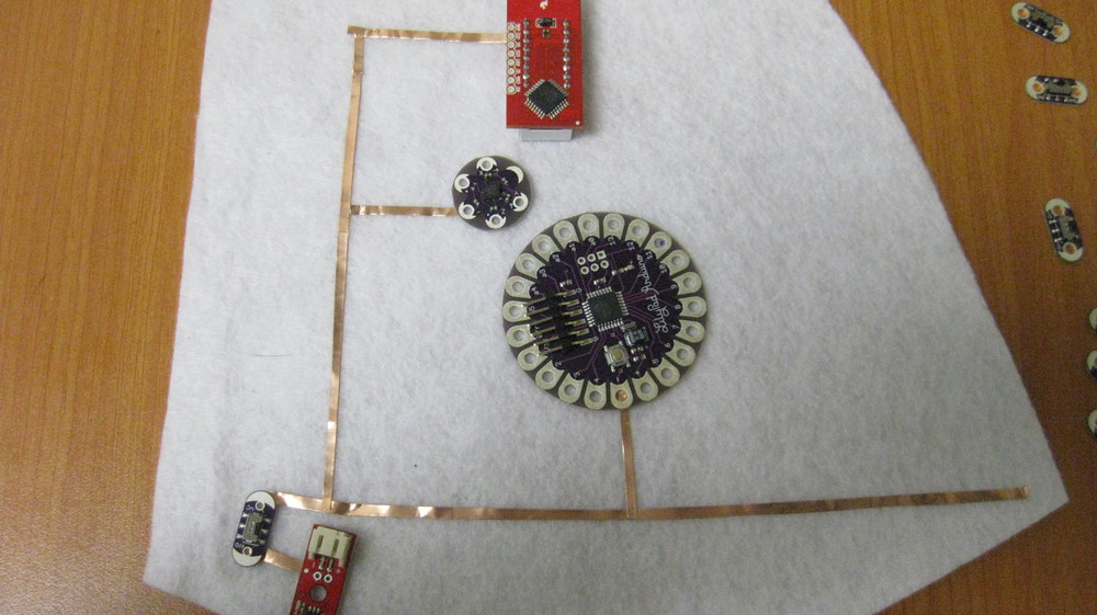
Our gauntlet circuit is going to look a little something like this:
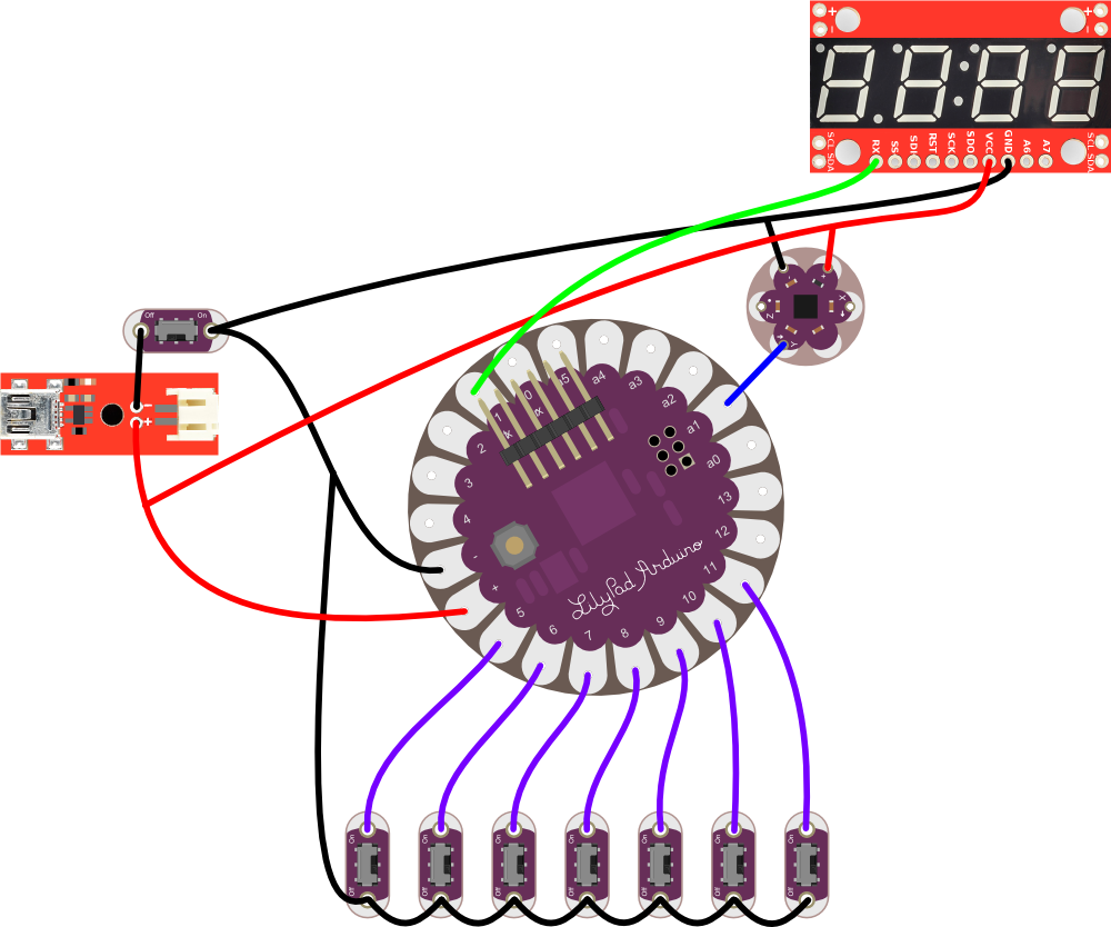
One of our switches controls current flow out of the battery, the other seven switches are connected to the LilyPad Arduino pins 5-11. The Y-axis of the accelerometer connects to "A1" of the LilyPad, and the "RX" pin of the display connects to "1" ("tx") of the LilyPad. The rest of our connections are just power and ground.
Bracer Preparation
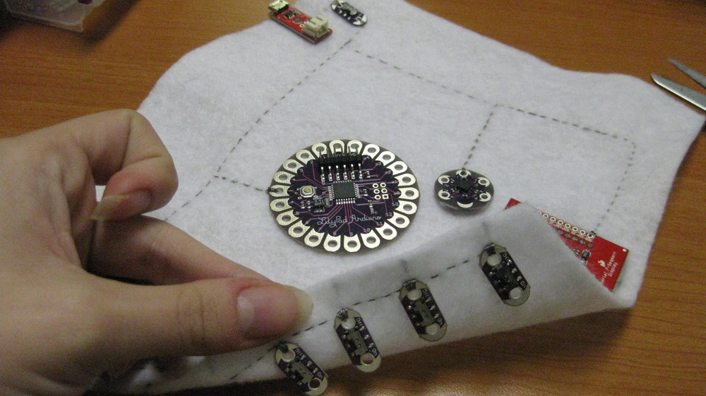
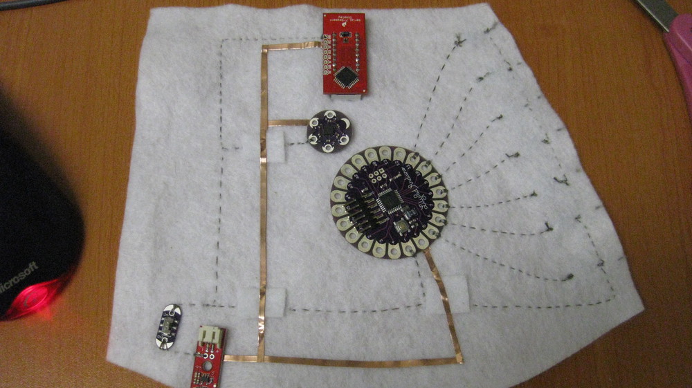
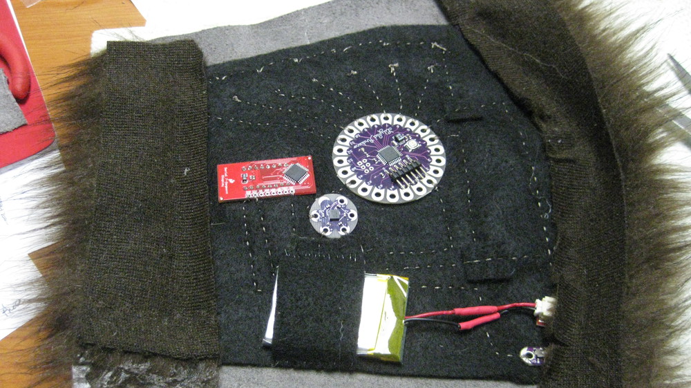
Start with your bracer pattern. You can be as simple or as complicated about this as you'd like. There are a number of bracer patterns online, or you can create a basic trapezoid shape. Use the circumference of your wrist for the short side, the circumference of your forearm for the long side, and the length you'd like the bracer to be for the equilateral sides. Mine was about 9 inches long. If yours is shorter, you might have to condense my circuit a little bit to make it fit. You'll cut your leather to this size and shape, but let's start with the felt so that we can create the circuit. Cut the felt one inch smaller than the pattern on all sides, and lay out your circuit. It should look roughly like this:
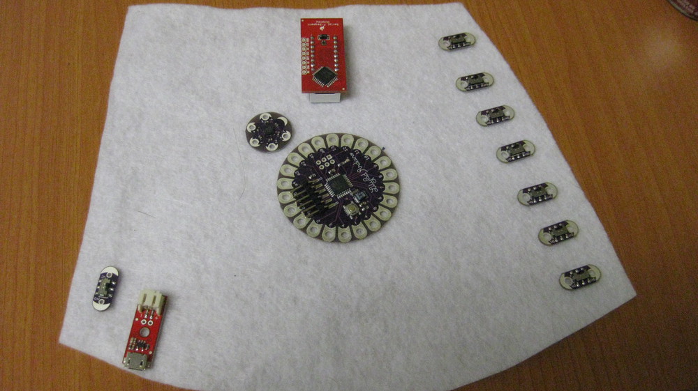
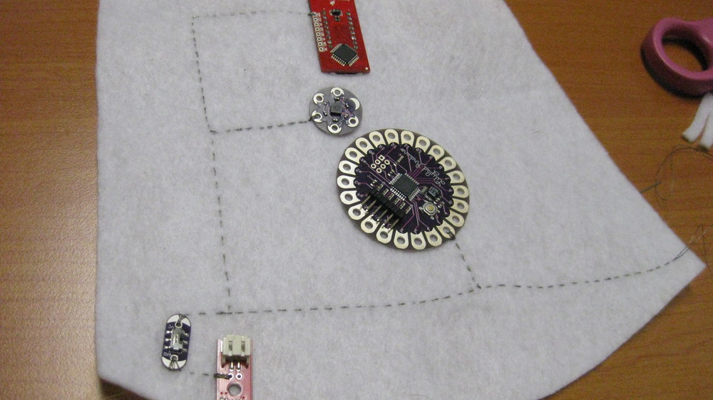
Make sure that you have the LilyPad Arduino Main Board oriented properly. You want to be able to attach everything properly. The 7-segment display will need to be flush with the fabric, so start by tracing around the face of the display on the fabric and then cutting this rectangle out.
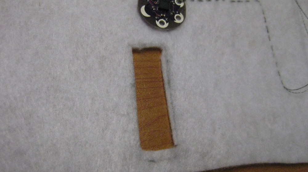
The side of the fabric you've laid the parts out on will be the back of the bracer. Press the display through the hole in the back to the front, like so.
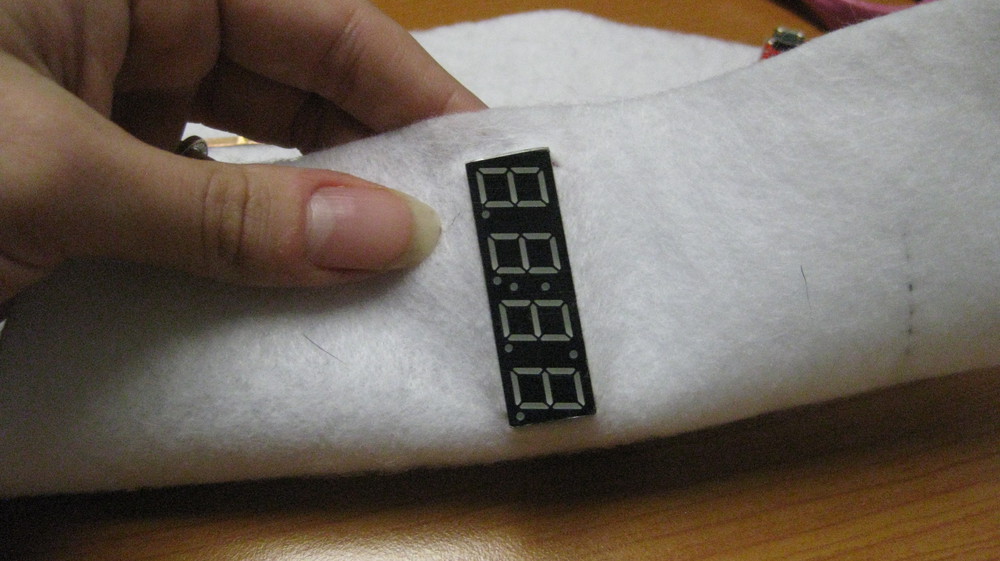
Now that the display is lying flush with the felt, so that only the red PCB is on the back side, it's time to begin sewing!
Assembly: Sewing Ground
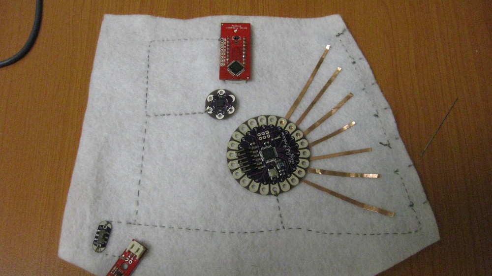
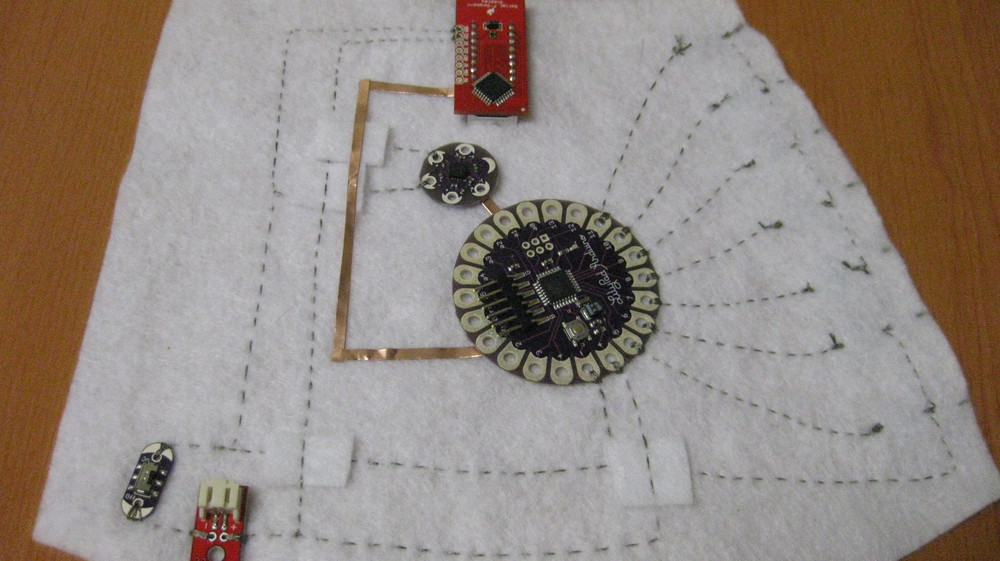
I've traced out the first connections you'll sew here in copper tape. I'm going to start with all of the negative traces. You'll be connecting all of the main components to each other and to ground on your power supply. Remove all of the switches on the right-hand side, leaving only the one next to the power supply, which is your LiPo Charger Basic.
Take a look at these connections. What you are doing is connecting every pin that is labeled either (-) or GND to each other, and then to one side of the power switch. Then connect the other side of the switch to the (-) pin on the power supply. This way, when you toggle this switch, you are creating and breaking the connection between the entire circuit and the power supply. This will be your on/off switch for the whole bracer. One trace goes off to the right side because we will be attaching it to the remaining 7 switches.
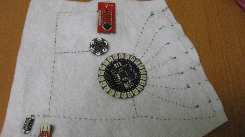
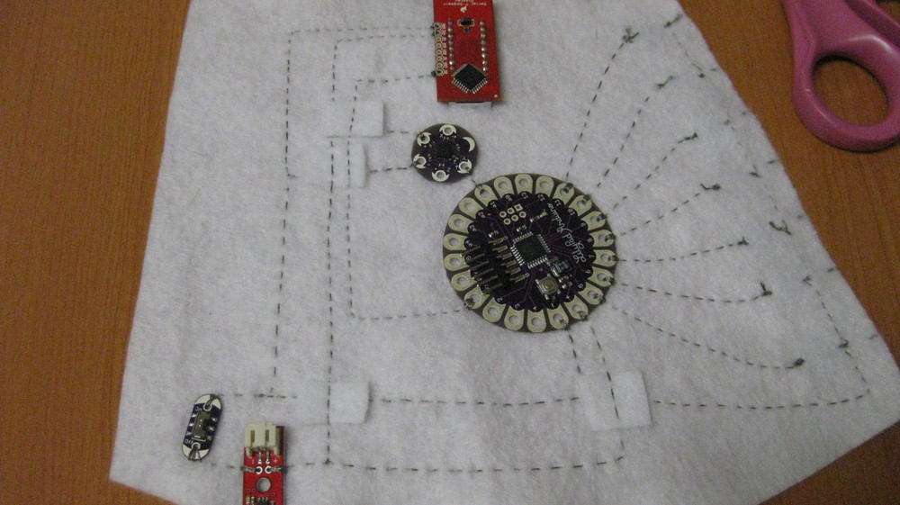
Here is a photo of my completed stitching on the negative trace. Feel free to skip to the end and see what all of the finished stitching looks like if you'd like to make changes the the circuit. As long as you leave room for all of the traces you see there, everything should be fine. You can move components into a configuration that works better for you or better fits the shape you have chosen for your bracer.
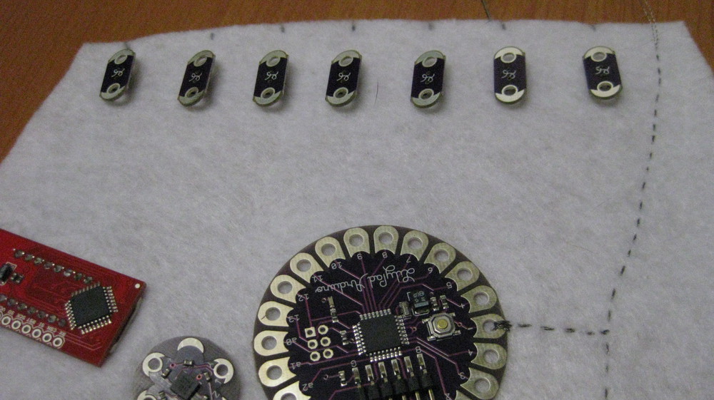
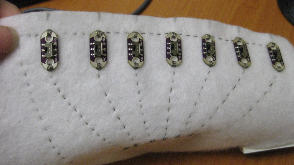
The next step will be adding the remaining switches. Line them up against the edge of the fabric. I tried to keep mine roughly equidistant. You can arrange them however you'd like, so long as you'll be able to connect one to each of the arduino pins 5-11. Mark where each button will go on the front and back side.
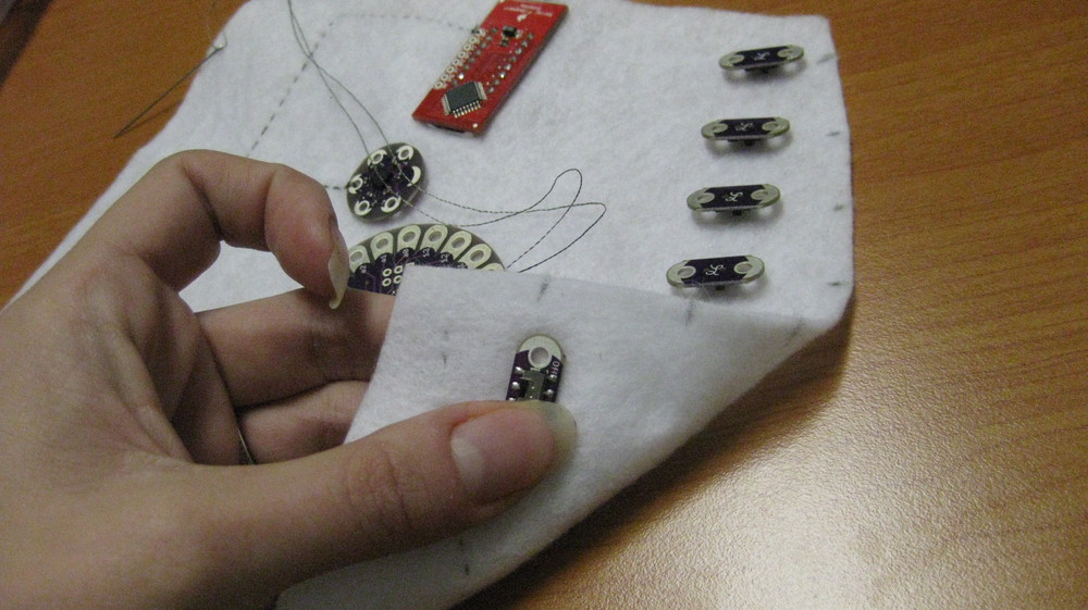
Tie your thread onto the long end you sewed from the negative circuit, and sew a line up the left side of the felt. Using the marks you made, move the button to the top side of the fabric, and sew down the 'Off' side until you have a line of all 7 of these switches sewn to each other and to the negative connections.
Tie off your thread, and start fresh for the next part.
Assembly: Stitches to Switches
Next, we're going to sew the other side of each button to one of the numbered pins on the arduino. Like the ground connections, we start by laying out each trace with copper tape.
I used pins 5-11. If you've chosen a different switch layout, you can use different pins. You'll just have to make a few small changes to the code.
Make sure that your thread ends are cut nice and short next to the switch. It's important that the thread on one side of each switch not come in contact with the thread on the other side.
Double check that each switch is connected to an Arduino pin on one side and to ground on the other.
Assembly: Sewing Power
We're going to move on now to the positive traces. Connecting all of the pins labeled either (+) or VCC to each other. Take a look at the traces I've laid out in the copper tape. You can see that in three places, this trace is going to cross over places where you laid down negative trace. In those places, I've put down small pieces of felt to act as bridges. It's going to be critical that these traces not come in contact with each other, so cut each bridge big enough to ensure this. Be very careful when you're stitching over them that you either skip entirely over, or stitch very near the surface, so that your top trace doesn't go all the way through the bridge fabric and contact your bottom trace.

Here's that portion finished, with the felt bridges in place. Now, you've got your switches connected entirely, and you've got power and ground attached to all of your boards. You're missing an input from the accelerometer to the Arduino and an output from the Arduino to the serial display, so we'll do that next.
I've laid the traces out in copper again. I'm connecting the Y pin on the accelerometer to the A1 pin on the Arduino and the TX pin on the Arduino to the RX pin on the serial display. Connecting the accelerometer up is a snap. That's a very short, simple connection if you've set the circuit up the way I have. If you've made changes, it could be different. Connecting the serial display up is a little more tricky, because you're going to have to cross a few other traces again. I reused the edge of one of my bridges over the negative trace and added another one over the positive on the way to the display.
That's all of your connections. Now we just need to upload the code!
Adding the Code
This code is going to tell the Arduino to roll a random number when it gets input from the Y-axis of the accelerometer. The limit of the random number is determined by which switch you flip. You can certainly make any changes to this code that you'd like, but it will work as it is if you'd rather not. Hook up your FTDI board to your computer and the Arduino board. Then cut and paste this code (or download it from here), and upload it to the LilyPad.
language:c
/* Accelerometer controlled Random Number Generator using LilyPad
Arduino and accelerometer

by: John Trepke and Brad Woodward 1/31/12
SparkFun Electronics
created on 1/31/12
license: Beerware- feel free to use this code and maintain
attribution. If we ever meet and you are overcome with gratitude,
feel free to express your feelings via beverage.

Arm movement will generate a random number between one and
selected maximum.

Hardware: LilyPad Main Board
*/

const int buttonPin1 = 3;             // Switch #1 on the DIP switch is digital pin3 on Arduino.
const int buttonPin2 = 4;             // Switch #2 on the DIP switch is digital pin4 on Arduino.
const int buttonPin3 = 5;             // Switch #3 on the DIP switch is digital pin5 on Arduino.
const int buttonPin4 = 6;             // Switch #4 on the DIP switch is digital pin6 on Arduino.
const int buttonPin5 = 7;             // Switch #5 on the DIP switch is digital pin7 on Arduino.
const int buttonPin6 = 8;             // Switch #6 on the DIP switch is digital pin8 on Arduino.
const int buttonPin7 = 9;             // Switch #7 on the DIP switch is digital pin9 on Arduino.
const int accel = 1;                  // Accelerometer's Y axis is anolog pin 1 on Arduino

int highnum = 0;                      // Variable to hold the high value for 'random()'
long ran;                             // Variable to store random number in

void setup() {
  pinMode(accel, INPUT);              // Sets analog pin 1 to input.
  pinMode(buttonPin1, INPUT);         // Sets digital pin 3 to input.
  pinMode(buttonPin2, INPUT);         // Sets digital pin 4 to input.
  pinMode(buttonPin3, INPUT);         // Sets digital pin 5 to input.
  pinMode(buttonPin4, INPUT);         // Sets digital pin 6 to input.
  pinMode(buttonPin5, INPUT);         // Sets digital pin 7 to input.
  pinMode(buttonPin6, INPUT);         // Sets digital pin 8 to input.
  pinMode(buttonPin7, INPUT);         // Sets digital pin 9 to input.
  digitalWrite(buttonPin1, HIGH);     // Sets digital pin 3 HIGH.
  digitalWrite(buttonPin2, HIGH);     // Sets digital pin 4 HIGH.
  digitalWrite(buttonPin3, HIGH);     // Sets digital pin 5 HIGH.
  digitalWrite(buttonPin4, HIGH);     // Sets digital pin 6 HIGH.
  digitalWrite(buttonPin5, HIGH);     // Sets digital pin 7 HIGH.
  digitalWrite(buttonPin6, HIGH);     // Sets digital pin 8 HIGH.
  digitalWrite(buttonPin7, HIGH);     // Sets digital pin 9 HIGH.

  Serial.begin(9600);                 // Start a 9600 baud Serial
  randomSeed(analogRead(0));          // Seed 'random()' using an unused analog pin.

  Serial.print("v");                  // Reset the display
  Serial.print(0x7A, BYTE);           // 'Brightness'
  Serial.print(0x00, BYTE);           // = MAX!

  delay(100);                         // Wait 0.1 second
  Serial.print("d8d");                // Send "d8d" to the display.
}

void loop() {
  if (analogRead(accel) > 400) {            // First trigger
    for (int num = 0; num <= 100; num++) {  // 100 cycles
      if (analogRead(accel) < 300) {        // Second trigger
        trigger();                          // let's Roll!
      }
    }
  }
}

void trigger() {

  if (digitalRead(buttonPin1) == LOW) {
    highnum = 5;                      //If switch #1 is flipped on, random 1-4.
  } else if (digitalRead(buttonPin2) == LOW) {
    highnum = 7;                      //If switch #2 is flipped on, random 1-6.
  } else if (digitalRead(buttonPin3) == LOW) {
    highnum = 9;                      //If switch #3 is flipped on, random 1-8.
  } else if (digitalRead(buttonPin4) == LOW) {
    highnum = 11;                     //If switch #4 is flipped on, random 1-10.
  } else if (digitalRead(buttonPin5) == LOW) {
    highnum = 13;                     //If switch #5 is flipped on, random 1-12.
  } else if (digitalRead(buttonPin6) == LOW) {
    highnum = 21;                     //If switch #6 is flipped on, random 1-20.
  } else if (digitalRead(buttonPin7) == LOW) {
    highnum = 101;                    //If switch #6 is flipped on, random 1-100.
  } else {
    highnum = 1;                      // Use highnum == 1 to denote no switches flipped
  }

  if (highnum > 1) {                  // Is a switch flipped?
    for (int num = 0; num <= 5; num++) {  // Roll 5 times, keep the 5th number
      Serial.print("v");              // Reset the display
      ran = random(1, highnum);       // Get a number
      if (ran < 10) {                 // If the random number is 1 digit,
        Serial.print("0");            // Put a 0 in front of it
      }

      Serial.print(ran);              // Show the number
      delay(100);                     // Wait 0.1 second between the faux-rolls
    }
  } else {                            // No switches flipped?
    Serial.print("v");                // Reset the display
    Serial.print("DURR");             // User == idiot
  }

  delay(1000);                        // Wait 1 second to prevent accidental re-rolls.
}
If you've never used Arduino before, check out our guides on what it is and how to install it. Also, check out our Beginning LilyPad Arduino tutorial.
Troubleshooting
All of the electronics are done! You can hook up a battery, turn it on, and check that it works. If you have problems, go ahead and cuss or throw something (soft, gently) if you want. It's cool -- I'll wait. It's frustrating when things don't work the first time, every time, but don't worry, we'll sort it out!
First, check for shorts. Look for ANY places where traces are touching each other that we didn't specifically say they should be connected earlier. Be particularly careful to check where your bridges are at if you put any stitches in them. It's easy to go too far through the fabric and end up with your top trace in contact with the bottom trace.
If you've got a multimeter with a continuity setting on it, that's a great way to check. Just put one probe in contact with your positive trace and one in contact with your negative trace. If it beeps, you've got continuity. There's your problem! Just use the resistance setting to poke around and find the point of lowest resistance, and there you'll probably find your problem. If the continuity check shows nothing, check around a few more places, then check continuity where you SHOULD have it -- from the positive pad of the power supply to the positive pads of the Arduino, accelerometer, and display, then likewise for the negative pads. Look for somewhere that the connection might be broken, and shore it up!
If everything DID work, that's great! From here on out, it's all crafty stuff.
Getting Crafty
If you haven't already, go ahead and cut the leather (or stiff fabric substitute) to your pattern, full size, which should make it about an inch larger than the felt on every side. If you want to put designs and embellishments on the front, it might be a good idea to wait until you've done all of the cutting you're going to do. I didn't do that, and as a result, ended up with my dragon design mushed up a little closer to my display than I would have liked it. Learn from my silly mistake!
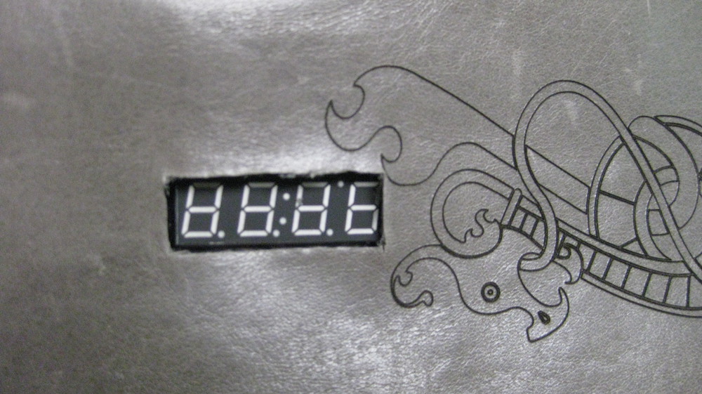
Remember that hole you cut in the felt to press the face of the display through? You're going to do that again now, but it's even more important that it be a nice neat hole and a good fit, since this is the going to be on the face of the bracer. I pressed the face of the serial display into the leather, traced around it with a pencil, and sliced it out with an Xacto knife. It's a little messy, and there are probably better ways of doing this. If you've got one, use it! The more finished this edge looks, the more professional the whole project will look. Really, that goes for all of the crafty parts of this project. If you've got more craft-fu than I do in these areas, use it! There's so much room for improvement!

Once you've got your hole cut, press the serial display through it. You should have the display on the front of the leather, and all of the rest of the electronics on the back side, still exposed and visible if you flip the whole thing over. At this point, I put a few dabs of hot glue on the red board to secure it to the back of the leather and keep things in the same place so that, when I cut the next holes, they'll be lined up properly.
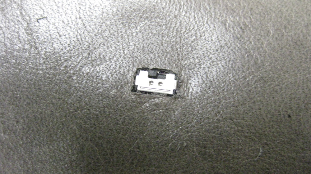
To cut the small holes for the switches, I just pressed the leather down against them, leaving indentations where the holes needed to be. This won't work with every fabric, but it should work with quite a few. If it isn't working for you, try feeling for them through the fabric with your fingers and gently tracing around each perimeter with pencil or chalk. Then, carefully cut that shape out with a craft knife. I did not cut out a hole for the entire purple board, just a very small hole so that only the silver switch shows through.

Note that my switches are not even REMOTELY in a straight line. I didn't worry too much about this, but it's entirely up to you where to put them. Straight line, not at all like mine, or even less of a straight line than I did. I've shown you where the traces need to go, and, as long as they get there, place them wherever you desire. In this photo, the felt isn't really attached to the leather. The only place where these layers are connected is the spot where I glued the display PCB to the leather. Everything else is just flopping around, as it were. That's because I want to be able to get to both sides of the felt after everything is put together, in case anything comes loose. The sad fact is that conductive thread stitches are just as vulnerable to tearing and loosening as any other stitches, and, over time, the circuit is going to need repairs depending on how frequently you use it. Make sure you're not making that too hard on yourself later!
I added a little bit of faux fur to the top and bottom edges of my bracer, because I wanted it to have a nice 'barbarian' feel to it. I made sure the fur was pointing off of the bracer in each direction. Then I cut the fur at the top edge off as short as I could, so I would have a nice flat surface to glue to the bracer, helping to keep it from sliding around.
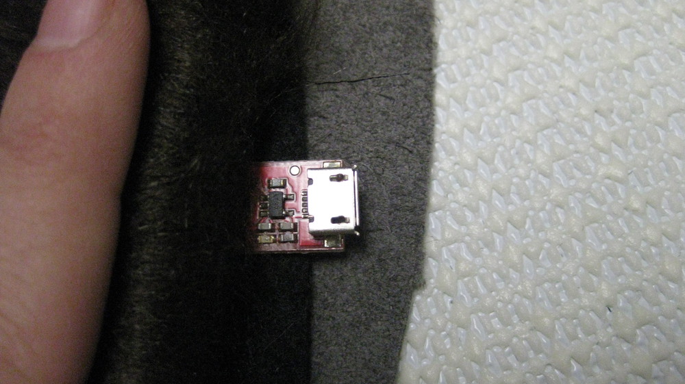
Make sure if you add fur or any other trim to these edges that you leave the mini or micro USB end of your charger board accessible. You want to be able to plug this in when the bracer needs to be charged up!

As a last touch on the back of the bracer, I added a small flap of a soft fabric. This part of the bracer has a lot of exposed electronics, and is going to be tied down close to your skin. I wanted to keep it from being scratchy, so this piece of fabric is just there to serve as a barrier between skin and electronics. I glued down only one edge of the fabric, so that it would be easy to get to everything underneath.
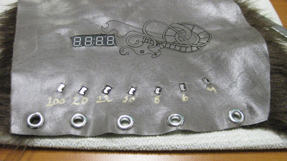
Last, you need to be able to close the bracer around your wrist. I used store-bought grommets and a leather lace. If you've got another way, absolutely go for it! Different styles of grommet tend to come with different application techniques. I used some pretty basic ones from the fabric store, which you pound in with a hammer and a little tool that comes in the package. You could pretty easily just attach leather or ribbon straps to both sides and tie them together, or use frog fasteners -- there are a lot of options here. If you use another method, attach them however the instructions say, and make sure that everything fits right before you attach anything permanently. You'll almost certainly want to borrow someone else's hands for that part. It's a pain to tie something around your own wrist!
Flip all of the number switches down, plug in your battery (if you haven't already), and flip the power switch on the underside up. You should get 'd8d' on the display. Now switch up one of the numbered switches and give your arm a shake. The bracer will roll a random number between one and the number on the switch you flipped up. If you've accidentally left more than one switch up, or no switches up, the display will show 'durr'.
Enjoy basking in the envy of your party!
Resources and Going Further
Here are some links if you're interested in checking out some similar e-textiles tutorials and projects:
- LilyPad Design Kit -- This series of tutorials aims to teach the basics of all things e-textiles.
- ProtoSnap LilyPad Development Simple Hookup Guide -- This tutorial is a hookup guide for the ProtoSnap LilyPad Development Simple a nifty LilyPad Arduino board, which includes LEDs and a buzzer.
- Getting Started with the LilyPad MP3 Player -- If you'd like to add sound or music to your e-textiles project, check out the LilyPad MP3 Player. With this board, you can use buttons to trigger an assortment of music files located on a µSD card.
Or, if you're looking for more, general electronics tutorials, check out some of these:
- Using the OpenSegment -- The OpenSegment Displays are a larger version of the Serial 7-Segment Display used in this tutorial. Want to make your gauntlet display bigger? Check this tutorial out!
- How to Use a Breadboard -- If you want to prototype a project without all of the conductive thread, a breadboard will be your best friend!
- How to Solder -- The alternative to breadboarding or conductive sewing is soldering. Soldering is a lot of fun, and it's easy! Check out this tutorial if you're interested in getting started.